Shake Rattle and Roll: Effects of Acoustical Resonance on Pumps and Pipes
By Allan R. Budris
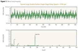
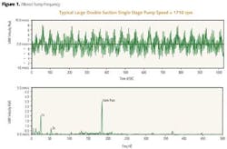
Acoustical pipe resonances, which can be excited by pressure pulsation from the pump (see Fig. 1), can cause excessive pump and pipe vibration. Acoustical pipe resonance (along with other potential vibration sources) have been referenced in two of the writer's prior columns on pump vibration (June 2008 and June 2012).
Although acoustic pulsations are not a frequent or common source of vibration in pumping systems, their occurrence is increasing with the growing popularity of variable speed pump drives. When resonant pulsations do develop in a liquid pumping system, they tend to be high in amplitude and can cause severe vibration problems. Therefore, it is very important to know how these pulsations behave in a liquid pumping systems, their frequencies, how to predict the acoustic responses of the pump piping system, and possible corrective actions.
Although hydraulic pipe resonance response problems are most often encountered on new installations, they can also pop up on existing installations when there is a system change, such as the addition of a variable speed drive, a new replacement pump, and/or different pump piping. Variable speed centrifugal pumps have a much higher chance of having vibration problems, since they generate a broad range of excitation frequencies. Pre-installation analyses and field testing may need to be performed to avoid this problem.
Hydraulic Pump Vibration Excitations
The amplitude of hydraulic pump excitations, especially those at blade pass frequencies, is typically a function of one of two pump energy factors: "High Suction Energy" and/or "High (discharge) Energy." According to the Hydraulic Institute, pumps with heads greater than 650 ft/stage that require more than 300 hp/stage have High (discharge) Energy, while the writer's last two WaterWorld Pump Tips columns (December 2012, January 2013) define High Suction Energy. The pressure pulsation excitations generated from either High (discharge) Energy, or High (or Very High) Suction Energy pumps both occur at impeller vane-pass frequency, and each can cause destructive acoustic pipe resonant vibration. This occurs when these high-energy (pump vane-pass) frequency excitations correspond with the frequency that will generate a standing acoustic wave inside a fluid filled channel.
The most common pump suction hydraulic exiting forces come from turbulence or cavitation within a pump suction, which can become a problem when the suction energy at the pump impeller inlet is high enough (see WW December 2012, January 2013). One of the ways to reduce pump suction energy is to reduce the pump speed with a VFD to achieve low suction energy. However, a VFD can also make it much more likely to excite a pipe acoustic resonance, so it can be a doubled-edged sword.
Discharge pressure pulsations are typically caused by the interaction between the different pressures on the leading and trailing surfaces of the impeller vanes at the impeller OD, and the casing cut-water (volute tongue). The higher the pump head and the smaller the gap between the impeller O.D. and the volute tongue, the greater the discharge pressure pulsations. These discharge pressure pulsations also occur at vane pass frequency.
Acoustic Resonance Response
Acoustic resonance can occur in suction and/or discharge piping, in the long crossover of multistage pumps, and in other fluid-filled channels, in response to a pump hydraulic excitation frequency. The phenomenon takes place when the return of a reflected pressure wave, generated by a periodic excitation, coincides with the generation of the next pressure pulse. In that case, a standing wave forms inside the fluid filled channel.
Amplified response causes of vibration are generally quite complex to analyze. A margin of safety should be provided between the typically highest pump excitation frequency, which is typically at impeller vane-pass, and major pipe hydraulic natural resonance frequencies. Typical minimum acceptable margins between the pump excitation and piping acoustic resonance frequencies are ±10-20%. The amplitude of the vibration response can be amplified 2.5 times or higher at or near a component natural (critical) resonant frequency The stronger the exciting force and/or the closer these exciting force(s) are to natural frequencies, the greater the vibration amplitude.
The channel length for acoustic resonance is determined by a reflective condition at the end of the channel opposite to the induction of the pressure wave. The channel length may be equal to quarter, half, or full wavelengths and multiples thereof. Normally only first and second harmonic need be considered. Typical reflection points include orifice plates, reducers or increases with 50% or more change, tees and partially closed gate or check valves. Long radius elbows do not reflect waves; short radius elbows and vaned elbows may reflect waves.
Possible offending pipe lengths can be identified using the formula for pipe, half-wave, acoustic resonance, which is as shown below:
f = ka/2L
where:
f = Resonance frequency (cycles/sec)
k = harmonic multiples (1,2, etc.)
a = acoustical velocity of sound (ft/sec)
L = Distance from pump volute cut-water to deflection point in piping (ft)
Note:
a = 4,720 ft/sec for rigid pipe, 4,365 ft/sec for 4 inch, schedule 40 steel pipe & 872 ft/sec for 4" plastic pipe (all with water as the liquid)
Corrective Measures
The preferred corrective measures are the ones that detune acoustic resonance conditions, providing a minimum of 10 to 20 percent of separation margin between wavelength curves and the hydraulic passage length. The following detuning features apply for channel acoustic resonances:
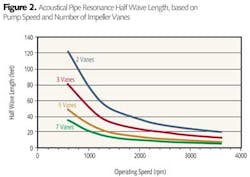
Change the vane count of the impeller (if the pump manufacturer offers this option) feeding the offending channel (pipe length). This changes the excitation frequency and therefore the wavelength (see Fig. 2).If detuning is not feasible, the applicable excitation levels can be reduced by means of implementing one or more of the measures listed below. These modifications do not eliminate the resonance condition and some vane pass vibrations may still exceed the maximum allowable levels.
- Reduce the pump suction energy level by reducing the pump speed, and/or increasing the impeller vane overlap, if it is less than 15 degrees.
- Increase the NPSH available to reduce cavitation (see WW January 2013).
- Cut back on the volute cutwater lips in a 30 degree to 45 degree under-file, resulting in a "scissoring" effect with the impeller vane twist angle. This, together with increasing the B-gap, is the most effective measure for reducing discharge excitation levels.
- Minimizing the volute cutwater (tongue) thickness, providing a "bullet-nose" type profile.
- Minimizing the impeller vane outlet thicknesses by means of overfilling.
- Install an Acoustic Filter, Suppressor, or Resonator, which can reduce the amplitude of acoustic resonant pressure pulsations (vibration), but they typically must be matched to the system and resonant frequency.
Conclusion
As noted above, pump vibration problems, especially those caused by hydraulic acoustic resonance, can be quite complex to identify and correct. Pre-installation analyses and field testing may need to be performed to avoid these problems. Consultants specializing in pump vibration may need to be brought in to evaluate the problem, by analyzing the filtered (vs. all-pass) vibration frequencies, such as shown in Figure 1, and to make the appropriate corrective recommendations. Specialists can also differentiate between a hydraulic acoustic resonance and a mechanical resonance.
References
1. "Analysis guide for Variable Frequency Drive Operated Centrifugal Pumps," Thomas F. Kaiser, Richard H. Osman & Ralph O. Dickan, Proceedings of the Twenty-Fourth International Pump Users Symposium, 2008.
2. "Acoustics in Pumping Systems," Robert McKee & Eugene Broerman, Proceedings of the Twenty-Fifth International Pump Users Symposium, 2009.
About the Author: Allan R. Budris, P.E., is an independent consulting engineer who specializes in training, failure analysis, troubleshooting, reliability, efficiency audits and litigation support on pumps and pumping systems. With offices in Washington, NJ, he can be contacted via e-mail at [email protected].


