Water supply systems must ensure that they remain isolated from drainage systems, groundwater, storm sewers, and sanitary sewers. Should the flows from any of these places enter a water main via siphon or backflow, the drinking water supply could be contaminated. A backflow prevention device keeps this from happening by isolating the water main from potential sources of contamination.
WATER SUPPLY BASICS AND LOCAL CODES
A city’s water supply system consists of a few basic components. First is the water source. This can be groundwater extracted by a well field or a surface water source such as a freshwater pond, lake, man-made reservoir, or major river. Second is a system of conveyances such as aqueducts and water pipelines to transport the water from the source to the treatment plant. Third is the treatment plant, a mechanical and hydraulic facility that removes impurities (such as silt and organic materials) to make it potable. Fourth is a system of conveyances that deliver treated water from the plant to homes, businesses, and industries. Lastly there is a series of water storage structures (towers, tanks, and cisterns) that hold excess water and provide surge storage capacity to the overall water delivery system as it evens out discharge flows.
The conveyance system consists of a series of branching and looping pipes, starting with the large water mains. Water mains carry the bulk of the water flows and vary in diameter from 6 inches to 8, 10, 12, and 16 inches. These water main pipes (and their fittings and appurtenances) are made from a variety of materials: plastics like PVC, HDPE, cast iron, ductile iron, copper, steel, asbestos cement, and reinforced concrete. Each pipe material has its advantages. Reinforced concrete is usually reserved for those extremely large watermains since concrete can be cast in large sizes relatively cheaply compared to metals or plastics. PVC is both durable and flexible while being lightweight and corrosion resistant.
Pipe wall thickness (the dimension that determines a pipe’s structural strength against applied loads and interior pressure) also varies with specific applications (depth of burial, type of aggregate pipe bedding, width of the trench, overburden and traffic loads, etc.). The typical thickness rating for PVC pipes are usually Schedule 40 or Schedule 80, a rating based on the ratio between a pipe’s diameter and wall thickness. HDPE pipe is similarly rated by its standard dimension ratio number. Iron pipe is described by its iron pipe size number with the outside diameter as its controlling dimension. Though cast iron pipe is often found in older water mains, it is not used much for new installations as it can be susceptible to corrosion and vulnerable to brittle cracking. It has largely been replaced with more flexible and shock-resistant ductile iron pipe. Steel pipe is lighter, less brittle, and more corrosion resistant. But it is also much more expensive and susceptible to temperature strain. Asbestos pipe has dropped from favor since asbestos (a known carcinogen) is suspect for both health and the environment.
Branch pipelines split off from the main at regular intervals via tee fittings that transition to smaller sizes varying from 0.5–6 inches in diameter depending on the required flow rate. These pipes pass through a water meter, which records its flow rates as it reaches its end use point. These direct service pipelines are usually made from Type K copper tubing, but lead pipes remain in widespread use.
The normal operating pressure range for water pipelines is 50–80 psi, with maximum pressure not exceeding 100 psi to protect residential piping. During circumstances in which pressure must exceed 100 psi (such as pressure testing of newly installed pipe) adjacent and connected service pipeline must be protected with pressure reducing valves. Operating pressures may also vary due to pump starts and stops, power failure, and valve operations—all of which can cause flow surges and even water hammer effects. The minimum required air pressure at discharges and faucets is 14 psi (atmospheric pressure) if exposed to an air gap or 20 psi at submerged discharges. Rural or isolated water users may need to use a booster pump to properly pressurize their water delivery system.
Many major cities have established strong backflow prevention programs. Toronto, Ontario, enacted its Water Supply Bylaw (Municipal Code, Chapter 851) on October 22, 2007. The act addresses backflow prevention to ensure the safety of drinking water and enforces standardized backflow prevention across the city. It was passed in response to the Canadian Safe Drinking Water Act and Ontario Ministry of the Environment regulations that mandate water purveyors to protect the water supply. It covers industrial, commercial businesses, institutions, and hospitals, as well as multi-residential apartment properties of five or more units, which must install backflow devices on all connections to City of Toronto water supply pipelines. Each is assigned a different hazard classification from severe risk (hospitals) to moderate risk (restaurants). Individual homes are not covered by the law as they represent the lowest hazard potential.
In the US, EPA holds local water suppliers responsible for maintaining potable water systems. New York City has enhanced its water code with a backflow prevention program. This includes a water-quality monitoring program and regularly performed sampling throughout the city to ensure all relevant State and federal standards are met. New York City’s Department of Environmental Protection aims to prevent cross-contamination before it occurs by means of an inspection initiative, which requires businesses to install, operate, maintain, and regularly test backflow preventers. This work has to be overseen by a professional engineer or registered architect and installed by a licensed master plumber.
SOURCES OF CONTAMINATION
Contamination of potable water supplies can occur at points called cross connections. These can occur both internally and externally. The internal cross connection with the greatest potential for large-volume water cross-contamination is a building’s fire control system. Given the large amount of water involved, it is vitally important that the connection between the pressurized water main and the sprinkler system with its water tank reservoir is equipped with a backflow prevention device. Internal cross connections can also occur at kitchen sinks, and within appliances such as dishwashers, clothes washers, and water heaters. These must be designed with internal piping configurations that prevent backflow.
External sources of contamination include groundwater, sewer lines, blocked drain lines, septic tanks, swimming pools, fish ponds, drinking troughs for farm animals, lawn sprinkler systems, water wells in addition to the water supply utility, and even buckets containing chemicals if a connection (usually via a hose pipe) is provided. Combined storm and sanitary sewers are especially vulnerable to backflow when excessive precipitation causes the sewer to back up into adjacent basements. Recycling tanks that are used to collect and reuse household graywater from rainfall, laundry, or showers can also be a source of cross-contamination.
An example of a simple internal design feature that prevents backflow can be found in every kitchen sink. It is called an air gap, and it’s mandated by plumbing codes. This is a vertical separation between the discharge end of the faucet and the maximum high water level in the sink. Generally speaking, an air gap is any separation between the end of any water outlet or discharge point and the flood level elevation within the receiving receptacle. According to plumbing code, the air gap has to be at least one inch vertical distance or as high as twice the diameter of the faucet or discharge pipe (International Residential Code 2003). This prevents dirty graywater in the sink from being siphoned back up the faucet and out into the water distribution system should a drop in pressure occur in the water supply line or water main.
WHEN DOES A BACKFLOW OR SIPHON OCCUR?
Backflow is the backwards flow of fluids (liquids or gasses) in a piping system opposite to their intended flow direction. There are many potential sources of backflow pressure including boilers, power washers, heat exchange radiators, sprinkler systems, and pumps in general. Loss of pressure in a water main is often caused by a break in the pipeline from shifting, excavation, vibratory equipment, vehicle loadings, failed valves, broken fixtures, or mechanical failures at a water supply pump station. Preventing the resultant backflow condition prevents the flows of contaminants, suspended solids, and dangerous chemicals form entering the water supply. Backflow is similar to someone sucking on a straw as contaminants are pulled into the water supply system. This situation is often referred to as “indirect cross-contamination.”
Back pressure, as opposed to backflow, is more like someone blowing air into their straw causing their drink to bubble and froth. This happens when, for example, a source of natural gas enters the water service pipelines and can be carried into the receiver of water service via a discharge pipeline or sink faucet. It can result in flames coming out of a kitchen faucet. Since the gas entering the system has to be at a higher pressure than the water pipeline, this only happens in locations where large gas extraction operations are occurring. This situation is referred to as “direct cross-contamination.”
In water supply systems there is a rare situation call back siphoning. This occurs when a faucet, hose, or pipe valve is left open and its open discharge end is submerged in dirty water. The back siphonage occurs when there is a sudden loss of water pressure in the supply pipelines while the open discharge end is submerged. As a result, the dirty water in the sink or tank gets sucked back into the water supply pipeline. The contaminants diffuse thought the adjacent water pipelines and can contaminate an entire water supply system. Even small-scale sources of contamination from individual households can have a serious impact. Given strict water-quality standards mandated by EPA, state regulatory agencies, and city water codes, a small amount of contaminants may render a water supply unusable. An even worse situation occurs when back siphonage draws dirty water out of a groundwater well or a water storage tank.
TYPES OF BACKFLOW PREVENTERS
Aside from the air gap between the faucet and sink, there are several types of mechanical pipe fixtures that provide backflow prevention. These include barometric loops, double check valve assemblies, double check intermediate atmospheric vents, reduced pressure zones, and vacuum breaker assemblies. Their use depends on the situation and needs.
The simplest is the Barometric Loop. This is merely a section of pipe that rises 35 feet above the service pipeline and then loops down to reconnect to the pipeline. For water at standard atmospheric pressure, the maximum siphon height of a column of water at sea level is approximately 34 feet. By extending this loop 1 foot higher than this maximum, it effectively prevents siphonage from occurring. Though it has a simple design and does not require check valves, it cannot be used to prevent back pressure and its excessive height makes it impractical for most applications.
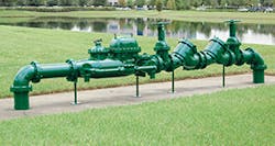
The most common backflow preventer device is the double check valve assembly (DCVA). It protects against both back pressure and back siphonage conditions. This assembly includes two single independently operating check valves located in line with four test cocks to test the water tightness of each check valve. This allows an operator to ensure that it is not fouled or otherwise not operating correctly. Each check valve is spring-loaded and operates closed while under continuous water pressure which keeps the gate open. It takes approximately 1 pound per square inch to open the check valve. The force of the spring is sufficient to push through accumulated debris and gunk if necessary, something that cannot be done by a simple swing check valve. In the event of backflow, both check valves close, preventing reversal of flow.
A version of the double check valve is the double check with intermediate atmospheric vent. Designed for compact applications (0.5-inch to 0.75-inch residential service pipelines), it is basically a DCVA with a vent that releases pressure to the atmosphere located between the two check valves. The location of the vent between the check valves is called the air break chamber. Until water flows, the check valves and the vent remain closed. But when back siphonage occurs or the pipeline pressure drops to zero, the vent opens. This allows air to enter the air break chamber. Conversely, when back pressure occurs, the vent also closes but opens if one of the check valves cannot close due to fouling. At that point air enters the air break chamber causing a disruption in the water flow.
A reduced pressure zone (RPZ) backflow preventer is a fixture that consists of five separately operating valves. Two separate check valves are located in the intermediate zone. A differential relief valve is located between these two check valves and two watertight valves are at the ends. Four test cocks are located in the spaces between the five valves. Until water is turned on, the two check valves remain closed. Then they are opened by the water pressure. Since pressure at the inlet is greater than pressure in the intermediate zone, the differential relief valve remains closed. If back pressure occurs, downstream pressure increases and both valves close preventing backflow. If one of the check valves is clogged or gummed up so that it can’t close, leakage into the intermediate zone and pressure will cause the differential relief valve to open, expelling the water. If back siphonage occurs, pressure from the supply pipeline drops and opens the differential relief valve. This also drains water from the intermediate zone, keeping pressure at the discharge end lower than the inlet end. Simultaneously, the other check valve closes and prevents downstream water from backing up into the assembly.
The simplest of the mechanical backflow preventers, the vacuum breaker (VB), combines a moveable disc with an atmospheric vent. In the event of back siphon, the pressure in the valve will drop below atmospheric, and the vent will open, admitting air and breaking the siphon. A VB is usually installed downstream from the last valve in the system. Though simple in operation, it is not designed to prevent backflow from back pressure.
Which type is best for which situation? That depends on the potential for damage to a water supply system. Typical backflow potential is rated as “severe,” “moderate,” or “minor.” Severe situations involve a potential cross-connection that could release contaminants sufficient to cause death, spread disease, or impart toxicity. For severe situations, it is best to use an air gap or a reduced pressure zone device. Moderate situations involve potential contaminants that could be a nuisance or aesthetically unpleasant, perhaps imparting a foul taste or odor to drinking water. A double check valve assembly is suitable for moderate situations. Minor situations involve possible two-stage contamination between a domestic water pipe and any other water conveyance or storage structure that could become a moderate hazard. A suitable backflow preventer would be a dual check valve.
INSTALLATION AND MAINTENANCE
Installation is usually the sole responsibility of the property owner or contractor and it is not just a simple matter of hooking the device on the ends of a pipe. Permits are required from local governments; usually, auxiliary plumbing permits must be obtained when attaching a backflow preventer to an existing water service line. The backflow prevention assembly needs to be installed according to local building codes (usually state codes and county water authority specifications and procedures). The local codes will designate the location and depth of the backflow preventer installation (usually between the water meter and the building). In addition to the backflow preventer, a separator ball valve is often installed between the flow meter and the backflow preventer. This valve will shut off flow if necessary to allow maintenance, repair, and replacement of the backflow preventer.
The frequency of inspection and testing varies with application (irrigation, residential, industrial, commercial, etc.). Typically inspections should be performed at least annually for moderate and minor conditions, and more frequently for severe conditions. Inspections will determine if a valve is clogged, or if the backflow preventer is damaged or has been tampered with. Inspectors usually are independent contractors and plumbers who have been certified
by the state regulatory agency or appropriate municipal office. Test results are recorded and reports filed with the governing agency that will approve the results and keep them on file for public viewing.
MAJOR SUPPLIERS OF BACKFLOW PREVENTERS
Made from corrosion-resistant materials that can provide long-term durability, CLA-VAL’s line of backflow preventers shows that this principle can be applied to maritime applications as well as infrastructure on land. Their Model RP-2 M Shipboard Backflow Preventer operates with minimum head lass and is resistant to shock and vibration in accordance with Military Standards. As an RPZ device, the Model RP-2 M utilizes two poppet-type check valves and an automatic pressure differential relief valve. The valves close whenever the pressure at the inlet is 2- to 3-psi higher than the pressure in the intermediate zone. This pressure sensing is performed via internal porting.
Danfoss VLT Drives provide its new Danfoss Flomatic, a 6-inch diameter RPZ and DCV. It has a flange-to-flange, lay-length dimension of only 42 inches, and a lay-length of 46 inches. Retrofits are easy and installation costs are minimized thanks to the shorter lay-length. It is designed with a single-access cove and spring clips that hold the check valve assemblies in place. Built from corrosion-resistant materials, it utilizes unleaded bronze material in its manufacture.
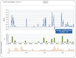
Monitoring and detecting leaks and backflows is as important as preventing them. Transparent Technologies offer that with their VN Virtual Network. Working with Verizon Wireless, VN provides Advanced Metering Analytics for water supply systems. By utilizing an existing communication system it requires no new infrastructure. It provides infinitely scalable deployment to remote, commercial, and industrial systems. It retrofits all meters without having to change them out, providing five-minute interval data and resolution down to 0.01 gallon. This data includes pressure drops, and changes in flow direction associated with back siphoning or backflow.


