Soil moisture monitoring can be useful as an irrigation management tool for both landscapes and agriculture, sometimes replacing an evapotranspiration-based (ET) approach or as a useful check on ET-based approaches since the latter tend to drift off target over time. All moisture sensors, also known as soil water sensors, measure a response to some soil property that is related to water content. A calibration equation is used to convert the measurement into a soil moisture estimate. Often the calibration is internal to the sensor or sensing system. Although individual sensors are available, the market is demanding moisture sensing systems that feed data into a central point using either wired or wireless telemetry. Sensing systems may be tied into a decision support system that further processes the data to provide an irrigation recommendation or even control an irrigation valve or system directly.
There are four main types of sensing technology: 1) Neutron counting, 2) Resistance measurement in a porous block buried in the soil, 3) Capacitance sensing, and 4) Time domain sensing.
The neutron probe counts neutrons slowed by collision with hydrogen atoms, most of which are in the soil water (H2O). The source of neutrons is slightly radioactive and is regulated such that safety training and licensing to possess a neutron probe are required and costly. Also, the neutron method is necessarily a manual method since the probe cannot be left unattended. Due to its accuracy when calibrated, large volume of measurement, lack of interference from salinity and temperature, and easy measurement at multiple depths in the soil, the neutron probe is still used by some consultants, particularly for high-value crops and where the needed access tubes can be left in for multiple seasons—this occurs despite the high costs of manual labor and required licensing/permitting and training.
The resistance sensors include granular matrix sensors and their cousins, gypsum blocks, which are buried in contact with the soil at whatever depth(s) are of interest (think root zone). The porous sensor body comes into equilibrium with soil moisture such that the sensor body dries as the soil dries, and becomes wetter as the soil is wetted. An alternating voltage is passed through two wires embedded in the sensor but separated by part of the sensor body. The electrical resistance between these wires increases as the sensor body dries and decreases as the sensor becomes wetter. The resistance readings can be manual or automated. The measured resistance is better related to the soil matric potential than to the soil water content. Since plant water uptake is in direct correspondence to the matric potential, these “resistance” sensors are fairly direct indicators of plant water need. But since the water content is not sensed, the data cannot be directly used to indicate how much to irrigate. Resistance sensors have been widely adopted in horticultural and landscape irrigation, although issues with loss of soil contact can occur in some soils.
The other two major types of soil water sensors respond to soil electrical properties, including the apparent permittivity (the ability of an electromagnetic field [EMF] to move through the soil) and the bulk electrical conductivity (BEC). Both the permittivity and the BEC increase with water content, although the permittivity increase is nonlinear. The BEC is dependent not only on water content but on soil temperature, which can bias readings from sensors sensitive to BEC.
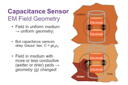
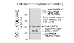
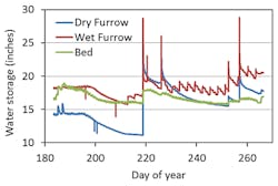
The most common of these “electromagnetic” (EM) sensors operate by imposing an oscillating EMF on the soil and measuring a frequency response. These “capacitance” sensors essentially couple a capacitive element with the soil and monitor the frequency changes driven by changes in the coupled soil electrical capacitance. Capacitance is calculated from the frequency measurements. The capacitance is influenced by both the permittivity and the BEC, but also by the shape and extent of the EMF that permeates the soil around the sensor element—the degree of coupling. The shape and extent factors are known as the “geometric factor” in the electrical engineering equation for capacitance, and they affect the value of the capacitance and the sensed frequency. Except for uniform sands, agricultural soils generally have enough small-scale (inch scale) variability in structure, water content, and BEC to substantially influence the geometric factor beyond the effect solely of bulk water content, resulting in biased readings (Figure 1). Also, changes in soil temperature directly influence BEC as do changes in salinity that may occur during an irrigation season or even in response to a single irrigation. For these reasons, the capacitance sensors generally are not sufficiently accurate to allow successful irrigation management following the management allowed depletion (MAD) paradigm that requires accuracy (Figure 2). They do provide useful information on general trends in water content, and when deployed at multiple depths they can indicate the depth of wetting due to irrigation and precipitation. Irrigation managers may find these kinds of information invaluable as aids to timing and general management of irrigation operations.
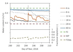
The other type of sensors that respond to soil electrical properties are those that measure the travel time of an electrical pulse along a metal rod in contact with the soil. The electrical engineering equations that describe how these sensors operate do not include a geometric factor, so the shape and extent of the EMF permeating the soil do not affect the travel time. For these time domain sensors, the travel time is a linear function of water content in most agricultural soils, but with some differences among soils in slope and intercept of the calibration due to soil texture. Soil BEC and temperature have minor effects on the travel time, although very high BEC values can prevent measurement of the travel time. Until recently, the time domain sensors were mostly used only by scientists due to the complex and expensive time domain reflectometry (TDR) equipment needed. However, the ubiquity of high-frequency electronic chips in the cell phone industry has now allowed miniaturization of the TDR circuit to fit into the head of a sensor that can be inserted into the soil. This both greatly reduced expense and eliminated the complex coaxial cabling and multiplexers need for traditional TDR. Direct coupling of the TDR circuit and the sensor electrodes (metal rods) improved the accuracy of the method and expanded the range of BEC values over which the TDR method can reliably measure travel time and sense water content. These true-TDR sensors are accurate enough for MAD-based scheduling and can be installed at depths as needed (Figure 4). In tests of several resistance, capacitance, and time domain soil water sensor-based irrigation controllers under field conditions, the time domain sensors were the only ones that consistently and precisely controlled irrigation.
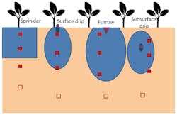
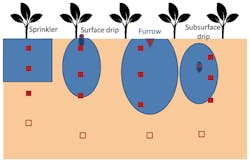
All sensing technologies are affected by the quality of sensor installation, with poor installation practices causing both under- and over-reading (e.g., unwanted preferential water movement to the sensor). Sensor placement relative to irrigation inputs is also key to successful management (Figure 4), including detection of overwatering or management of salts (Figure 5). Sensors in all technologies can be installed at user-chosen depths to assess soil water in the rooting zone, whether that be for shallow-rooted turf or deeper rooted crops, shrubs, and trees. Some vendors make this easier than others. Examples are the granular matrix sensors and the new true-TDR sensors, both of which feature cylindrical bodies that can be fixed to lengths of PVC pipe for installation at different depths in auger holes. Another example is the type of capacitance sensor that can be installed within plastic access tubes, or that are incorporated within a cylindrical or tapered plastic tube. Although easy to install, these capacitance sensors exhibit the disadvantages previously explained.
Except for the neutron probe, sensed soil volumes are small, with the greatest response (90% or more) being to soil water within 1.5 inches or less of the sensor. Most modern soil moisture sensing systems include some form of telemetry for accessing data from afar. Integration into irrigation decision support systems varies by manufacturer, but third-party integrative platforms are appearing regularly and may be able to support the sensor system of choice. There are new developments in soil water sensors, wireless data transmission, and decision support systems almost daily. Choice of a soil water sensing system may be as much influenced by ease-of-use attributes as it is by the accuracy of the sensor. That said, inaccurate sensors have been shown to cause chronic under-or-over watering.
ACKNOWLEDGEMENTS This work was supported in part by the Ogallala Aquifer Program, a consortium between USDA-Agricultural Research Service, Kansas State University, Texas AgriLife Research, Texas AgriLife Extension Service, Texas Tech University, and West Texas A&M University.