Backflow preventers are critical for creating a safe water supply system. It’s important to examine the design, installation, and use of backflow preventers in the context of the overall water supply system operation. Certain parts of a water distribution system are more vulnerable to backwash and infiltration of contaminant-laden groundwater and run-off, and will have proportionally greater need for the services of a backflow preventer.
THE NEED FOR BACKFLOW PREVENTION
All water supply systems include several major components. The first major factor is the water demand load by the population being serviced. Though this is not necessarily a physical thing, it drives the design and installation of all other components in the water supply system. Water demand varies on a per capita basis along with season. Summer is generally a higher demand period than winter since personal consumption of water increases with heat, lawn and garden irrigation, recreational pools, etc.
The size of the population also affects water demand. According to Sankarasubramanian et al., “The median per capita water use per day is higher in rural counties than urban counties in all the climate regions, except in the Central and Southeast regions”1 with rural areas having less efficient water supply systems2 primarily due to the relative lack of financial resources to upgrade and maintain their systems. So, the higher per capita “consumption” of water in rural areas may include significant non-revenue water losses from their distribution pipelines. Such issues also factor into the need for backflow preventers at the points of use.
According to USGS data, Americans on average utilize about 80-100 gallons of water per capita per day (about 33,000 gallons per capita annually, or a total of about 355,000 million gallons per day). But this average doesn’t mean much when applied to particular water demand applications. Water demand also fluctuates with economic factors such as agricultural irrigation applications, factory process water consumption, commercial business operations and family/individual use in residential areas. USGS data indicates that “industrial withdrawals were an estimated 14,800 Mgal/d in 2015, about 5 percent of total withdrawals for all categories of use.” Further, agricultural and irrigation utilization comes to “118,000 Mgal/d, which accounted for 42 percent of total freshwater withdrawals” with livestock consumption accounting for another 2,000 Mgal/d. When factoring in all uses, the total (domestic, commercial, farming, etc.) average daily per capita water use comes to about 150 gallons per day.
The use of backflow preventers is tied to the water’s usage. Backflow preventers are used to ensure the safety and purity of the distributed water. Industrial water supply typically has a minimum standard of quality, depending on the industrial process in question. Agriculture on the other hand has less stringent water quality standards. But where backflow preventers are most essential is in the supply of potable water for domestic and personal use.
Demand loads, no matter what their use, must be met by an adequately sized water supply, which constitutes the second major component of a water supply system. With adequate storage tank capacity to meet variable peak load demand, the water supply source can provide a steady flow of water. During hours of low demand, the water flow can be used to refill storage towers, tanks and cisterns, which then provide water for emergency use and periods when demand exceeds the baseline pumping rate. A water supply source can take many forms, including groundwater extraction well fields, free-flowing rivers, natural or man-made ponds, artesian springs, ocean water desalination plants, and rainwater run-off collection systems.
Larger urban areas require both large and diverse or multiple water sources. These can be extensive groundwater extraction well fields providing water from underlying aquifers, surface bodies of water (including, lakes, ponds, man-made reservoirs), rivers with a flow capacity capable of meeting the community’s water needs, or water piped in from great distances such as the water supply pipelines servicing New York city that transport water from sources upstate.
The major dangers to a sufficient water supply — evaporation or fluctuations in flow — vary with the source. Groundwater is not impacted by evaporation (although groundwater levels may rise and fall with the seasons and differences in infiltration and recharge rates) while surface waters are chosen because they have a sufficient flow rate and/or storage capacity.
Once a large enough source of water has been identified and evaluated, the third major component of a water supply system comes into play: a system of pipelines to convey the water from its source to its consumers. The largest of these primary long-distance transmitting pipes are referred to as aqueducts. Typically constructed of large-diameter (10 feet or more) reinforced concrete pipe segments, and even tunnels lined with an impermeable coating, these are huge underground and aboveground pipes designed to carry bulk flow quantities of water to treatment plants, secondary storage facilities and distribution nodes where the flows are transferred to smaller-sized branch distribution pipelines. Most large cities need several aqueducts supplying water from diverse and geographically separated sources.
These branching distribution pipelines form networks and loops consisting of water mains and supply pipelines. Water mains range in size from 6 inches, to 8, 10, 12, and 16 inches in diameter. The pipelines provide water for entire neighborhoods as well as large commercial, industrial and residential complexes. Depending on the flow capacity, location and age of the pipe system, these pipelines are made from a variety of materials: polyvinyl chloride (PVC), high density polyethylene (HDPE), cast iron, ductile iron, copper, steel, asbestos cement, and even smaller-diameter reinforced concrete.
Distribution pipes transition to even smaller individual service pipes, carrying water to individual homes, apartment buildings, shops and businesses. Depending on demand, these pipes range in size from a half inch in diameter to 6 inches. Water enters the consumer facility via a water meter that records flow rates and water utilization for billing purposes. Individual service pipelines are typically made from plastic, lead or Type K copper. And it is here at the point of application where the installation of a backflow preventer can be critical.
And so, we see the transition from huge transport pipelines (aqueducts) providing water to entire cities to large distribution pipes (mains) servicing smaller communities or large facilities, to medium distribution pipelines and finally to small service pipelines. Each stage in the water supply and distribution system has to deal with differing flow rates, flow velocities and pressure heads, along with different levels of exposure to potential backwash or contaminant infiltration and the subsequent need for protection with backflow preventers.
Each type of pipeline has a different structural strength requirement depending on its overburden when set in its underground trench, which in turn depends on the depth of pipeline. Both strength and pressure requirements are met by varying the pipe wall thickness. Each type of material has an inherent strength characteristic and different rating scale: Schedule 40 or 80 for PVC, standard dimension ratio (SDR) for HDPE, iron pipe size (IPS) for iron pipe, etc.
Some pipe materials are cheaper than others; some are more brittle and prone to cracking, displacement or other types of structural failure. Other materials are prone to corrosion and rust while some are unaffected. Certain pipe materials have higher coefficients of heat strain, making them more vulnerable to structural stresses and strains as a result of temperature change and ice formation. And these differences dictate the potential need for backflow preventers.
The fourth and fifth major components of a water distribution system deal with the system support functions of water treatment and water storage. No natural source of water is pure enough and in sufficient quantity to provide a large community directly with aesthetically pleasing and potable water without the need for some level of treatment. As mentioned above, treatment facilities are located at the start of the conveyance system and receive water from the system’s source. Through the use of detention, settlement, chlorination, aeration, coagulation and flocculation, adsorption, filtration with porous media (sand) or membranes, and UV disinfection (and other hydraulic, mechanical and chemical processes), water is purified from the natural source and made fit for human consumption. Water slated for use in agricultural or industrial applications will tend to have lower standards of purity. It is the need to maintain these levels of purity necessary for human consumption that makes the use of backflow preventers so vital.
Storage facilities and surge tanks are typically installed at the terminus of the water conveyance system, usually between and aqueduct and the distribution water mains. These are facilities designed for the short-term staging of water supplies and include water towers, tanks, cisterns, secondary reservoirs, and lined ponds. These are best thought of as flow regulators rather than water storage units. Since water demand varies throughout the day while the pipe flow rates from the water source remain roughly constant, usage never exactly matches supply. As so for those periods where water flow is greater than demand (typically night-time hours), the excess water supply is safely and cleanly stored for later use when demand rate exceeds supply (typically throughout the work day, though with some variations from morning to afternoon and evening).
THE MECHANICS OF SIPHONAGE, BACKFLOW AND CONTAMINATION: WHAT HAPPENS AND WHY
Now that we have identified those points in the water distribution system most vulnerable to potential backflow, we can examine why these points are critical. Backflow into a piping system can be caused by either siphonage or applied pressure, with siphonage being the most common. A siphon is analogous to sucking through a straw, while pressure is like blowing through a straw.
It comes down to the action of a siphon. In its simplest form, a siphon is a tube in the shape of an upside-down U or J. One end of the tube is set below the surface of a reservoir supplying the water. This is the shortest length of the tube located between the reservoir and the high point of the tube. The second tube segment also has its open end immersed in a body of water, but this water level is lower than that of the water supply reservoir.
The siphon action is triggered by the difference in the weight of water in each half of the siphon tube. The length of tube in the supply reservoir is shorter than that discharging into the receiving body of water. The longer length of water weighs more than the shorter length and gets pulled down by the force of gravity. As it does so, it leaves a zone of low or zero pressure at the top of the siphon tube. This low pressure exerts a suction force on the shorter/lighter water in the supply end of the tube, dragging it up and over the top of the siphon tube. This sets the water flow in motion from the reservoir up and over the siphon tube into the lower receiving reservoir. This dragging of water from one end of the siphon tube to the other is made possible by the cohesion of the liquid, which prevents it from separating into two halves. In effect, it creates a daisy chain of liquid flowing through the tube.
Siphonage into a pipe system occurs when there is a decrease in supplied pressure to the water flow. The result is a backflow where liquid in the pipe segment flows backwards relative to the direction of the system’s water supply movement. This opposite flow is usually localized and can result from a loss in upstream pressure from, for example, physical failure of the pipe wall or its joints. Such physical damage is more common in smaller pipes subject to vehicle traffic on overlaying roadways, vibrations from adjacent heavy equipment operations, settlement of nearby soil or shifting foundations, the wear and tear of pipe appurtenances such as valves and meters, etc. The result is a complete breakage, dislocation or cracking in the pipe that allows water to escape. Sometimes no apparent physical damage to the pipe is required, just the mechanical failure of a key pump whose shut down results in a significant pressure drop across the pipe network.
The backflow created by negative pressure or siphoning is potentially very dangerous because it can suck contaminated water back into the pipe distribution system where it can render impure most if not all of the local water supply system. This process is referred to as “direct cross contamination” and the impurity can come from water discharged by the system (as when a faucet is left open and its opening is submerged below the surface of dirty water in a sink, basin or tank) and its supply pipeline is subjected to negative pressure. Similarly, a crack or dislocation in a buried pipeline can result in an infusion of contaminated groundwater laden with soil bacteria, decayed organics or soil particles. Surface water entering a pipeline can contain fertilizers, pesticides, fungicides, insecticides, animal waste, and other chemicals. Even small quantities of contaminants can render drinking water unpalatable if not cause it to completely fail to meet safe drinking water standards. The sight and taste of impacted water is enough to destroy public trust in the entire water supply system.
There are two broad categories of sources of potential cross contamination: internal and external. Internal sources include the aforementioned kitchen sinks, basins, tanks, toilets, fire control system water, water from ice makers, soapy water from sinks or floor cleaning tasks, and appliances such as dish washers, hot water tanks, radiant water heating systems, etc. External sources include rain water run-off from roofs and parking lots, groundwater, puddles of surface water, sanitary sewer pipelines, other water supply pipelines, septic tanks, underground storage tanks and cisterns, irrigation pipelines and ditches, fish ponds, natural bodies of water, lawn sprinklers, agricultural run-off from animal lots, drainage from compost piles, buried or aboveground chemical storage tanks, gray water from water recycling systems, and backup of combined overflow sewers during heavy rainfall events into building foundations and basements.
Contaminants can be man-made or natural as well as organic or inorganic. Biological contamination can be just as dangerous as contamination from toxic metals such as lead. Natural can include non-living (soil such as silts, clays and other sediments) or living agents (soil bacteria, feces, etc.). Inorganics comprise an entire list of metals listed in Federal Regulations 40 CFR, which includes an even longer list of organic chemicals ranging from fuel spills, oil and grease to drips of coolant and anti-freeze, to complicated long-chain polymers. And not every source is liquid in nature. Lead-contaminated paint can chip and fall to the earth and be absorbed into the soil.
HOW BACKFLOW PREVENTERS WORK
The need for backflow preventers is obvious, but how do they work and which designs are best for certain applications? Often the type and installation requirements are spelled out by environmental regulations and local statutes. Local building codes for example will require a vertical separation of at least one inch to form an air gap between a faucet opening and the highest possible water level in its sink or basin. The resultant gap breaks any potential siphon before it can occur, preventing contaminating water from being sucked back into the pipe system. Other laws can require the installation of more complicated and sophisticated backflow preventers. And the design of these mechanical devices installed to prevent backflow range from the relatively simple to the very sophisticated and complicated.
The simplest backflow prevention device is the barometric loop. This is just a non-mechanical pipe length forming a loop extending a minimum of 35 feet vertically above the water supply pipeline. The height is necessary to overcome the ambient air pressure (at mean sea level) of 34 feet of head (14.6959 psi). A loop of pipe this high prevents a siphon from forming. Its advantages are the simplicity of its design and lack of moving parts. However, it may be impractical in many situations to install a pipe segment of this length. Furthermore, a barometric loop will not prevent back pressure from forming as the result of a pump failure.
The simplest mechanical backflow prevention device is the vacuum breaker assembly (VBA). It has one moving part, a moveable disc attached to an atmospheric vent. In the event of a siphon, the pressure in the valve will drop below that of the outside air. This triggers the disc to open, allowing air to enter the valve and restore pressure equivalent to ambient atmospheric standard. This restoration of pressure breaks the siphon and prevents cross contamination.
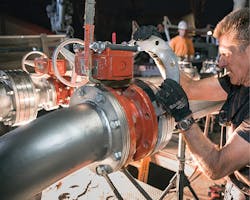
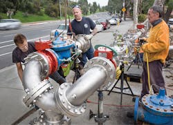
More complicated is the double check valve assembly (DCVA). This device has found widespread use since it prevents both siphonage and back pressure. The paired check valves are arranged in line with the pipeline and operate independently of each other. A set of four test cocks allow the operator to examine the valves and make sure they are not being forced open by accumulated debris. Each spring-loaded check valve is set to allow water at anticipated operational pressure to flow through. Should backflow occur, either due to siphonage or back pressure, the springs slam the valves shut tight, preventing the entrance of cross contamination water.
A modification of the DCVA is the double check valve assembly with intermediate atmospheric vent (DCVA-IAV). This design includes a passive vent situated between the two check valves. This venting to the outside ambient air creates an air break chamber, which allows for the release of pressure in excess of one atmosphere. In the event of siphonage or backflow, this air intrusion into the chamber creates a break in the water flow that would allow continued siphonage.
Lastly, the most complicated and sophisticated backflow preventer is the reduced pressure zone device. This device consists of no less than five independently operating valves (two check valves and a differential relief valve sealed off at both ends by water tight valves). Each valve acts as a back up system to the other four. During standard water flows at design pressure, the two check valves stay open and the relief valve is closed. The relief valve will spring open if either check valve is clogged and wedged open by debris or if siphonage occurs to the connected service pipeline. To prevent backflow, the downstream check valve will close. Such a sophisticated and reliable (if expensive) device is best used in critical areas where cross contamination could be a direct danger to life and health.
MAJOR SUPPLIERS
Zurn Industries: In addition to providing an extensive line of backflow preventers, the majority of Zurn Wilkins’ plumbing fixtures meet and exceed the standards established by the Safe Drinking Water Act and lead-free initiative. Recent changes to the Safe Drinking Water Act mandated that all commercial plumbing fixtures, valves, pipes, and fittings that are directly intended for human water consumption are required to be manufactured with less than 0.25 percent leaded brass content. Zurn Wilkins plumbing products that fall within this category have been designated “lead-free,” meaning they are compliant.
The types of backflow preventers the company provides include double check valve assemblies, double check detector assemblies (including stainless-steel models), and reduced pressure zone assemblies.
Its product line includes an equally extensive list of backflow assembly accessories, including building risers, replacement ball valves, gate and butterfly valves, flush fitting tools, test kits and air gaps. The company’s 350XL and 350 double check valve assemblies provide low health hazard backflow with ease of maintenance and are used in all market segments. A different model is its top-access double check valve assemblies, the 950XLT2/950XLT series. The top access makes it suitable for low health hazard applications that need ease of access during testing and repair. A variation of this design is the wye pattern design of the 950XL series, suitable for fire protection and irrigation water supply systems. Innovative design is also provided by its 450 series double check valve with its signature N-configuration, which allows for retrofit of large-diameter pipes in tight locations.
REFERENCES
1. Sankarasubramanian, A., et al. “Synthesis of Public Water Supply Use in the United States: Spatio-Temporal Patterns and Socio-Economic Controls,” Earth’s Future, 5: 771-788, 2017.
2. “Water Efficiency in Rural Areas Getting Worse, Despite Improvements in Urban Centers,” AGU100 Joint News Release, May 18, 2017.
