Care Needed in Selecting Fluid Flow Software
By Warren K. Brewer
Advances in computer technology have provided many tools to simplify the tasks faced by engineers, especially those responsible for designing and managing water and wastewater systems. But selecting the right software program for a particular application requires careful analysis.
Tools such as ABZ Inc.'s Design Flow Solutions software help solve fluid flow problems which would have been difficult and time consuming by hand. To be truly useful, however, these software tools must have a sound technical basis and address those issues that are important to engineers.
These issues include the accuracy of the software, the data included with the software, the type of problems that the software can solve, the flexibility to define problems, report capability, and support from the software vendor.
Software Accuracy
First and foremost, the software must calculate answers correctly. This doesn't mean addition and subtraction (although that must be correct too); rather, it means applying the proper equations for each problem. Even user-friendly software is of little value if the answers it calculates are wrong.
Concerns about how different software packages approach different problems can generally be answered by reading the sales literature for the product, testing the actual software, or asking the vendor questions. It is also valuable to perform simple tests with newly purchased software to verify the capabilities of the software, while at the same time learning the basics of using the software.
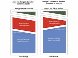
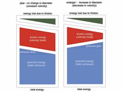
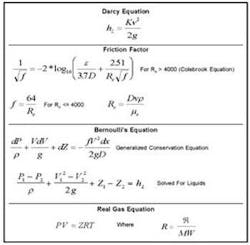
A common error in hand calculations and some software packages is not applying Bernoulli's theorem, or the derivative form of this equation for compressible problems, to account for energy conversion between static pressure, elevation, and velocity. This conversion occurs across any change in elevation or size (including "effective" changes in flow area in a tee).
When solved properly, static pressure generally increases when flow area increases due to the decrease in fluid velocity. When this conversion is not applied, the calculated pressures or differential pressures are wrong. A good software tool must automatically apply this equation, as well as other equations, to properly account for conversion of energy between different forms.
Other equations, such as those for calculating hardware resistance, depend on information that may not be known when the problem is specified. An example includes fittings that change flow area. The ultimate flow direction of each path must be known to correctly calculate the flow resistance; yet for cross-connects or other similar lines, the flow direction may not be known before the problem is solved.
Flow direction is especially difficult to determine when analyzing casualty or off-normal conditions. To avoid requiring that the engineer guess the flow direction, the software must be capable of selecting the proper equation during problem solution.
There are similar concerns with selecting a friction factor. A turbulent friction factor is generally used for valves and fittings, while one based on flow velocity is used for pipes and other conduits. This practice is based on actual test data and has been commonly used for several decades.
Some tools use equations for flow resistance that are based on flow velocity; while others choose the friction factor based on the component type. Either of these approaches is valid. What is not valid is to use a single friction factor across different hardware types and sizes.
Included Data
Even proper equations need good data. A good software tool will provide data for common hardware and fluids. This data should include pipe and tube information (sizes and surface conditions) and common fittings and valves.
On the fluid side, certainly water and common liquids and gases are desirable. There should also be the capability for the user to specify unique hardware and fluids to accurately model non-standard items. The ability to add such user-specified items to the program's database for future use, in addition to specifying for use in a particular problem, also is desirable.
Program Flexibility
An engineer typically faces many different types of problems. The information to be determined is often different from one problem to the next. A good software tool allows problems to be solved different ways, such as by specifying flow and solving for pressure drop; by specifying pressure drop and solving for flow; or by specifying pressure drop and flow and solving for required diameter.
An engineer must readily convert information between many different unit types. This requires a reference for conversion factors and, in hand calculations, often introduces errors due to transcription or misapplication of factors. A good software tool allows the user to specify and view information in different units.
Many fluid flow problems faced by an engineer involve a significant quantity of hardware and numerous flow paths. In these cases, it is important to choose a tool that allows these larger problems to be solved.
Software tools typically place limits on the number of flow paths, or pipe sections with similar pipe diameters (such that two pipes of different diameters connected together (with appropriate size change) may count as two flow paths. The size of problems that can be solved also can be limited based on the ability to display a problem on the screen. A good software tool allows the screen to be enlarged, reduced, and scrolled.
Reporting Capability
While solving problems is important, it also is important to be able to see the results. The engineer may want several types of information. First, a "big-picture" view of a system showing all of the flows and pressures is useful to understand system function and behavior.
Second, detailed information about each flow path and individual components is useful both for design of new systems and troubleshooting of existing systems.
It is sometimes important to consider the order of components in a flow path, particularly in situations where the fluid pressure approaches the vapor pressure of the fluid, where individual component pressure drops are important, or where fluid velocity within a flow path must be limited.
In these cases, a software tool that considers the order of components within a flow path and allows the user to see values for each individual component is important.
Technical Support
However good the software, there is always a need for technical support, both for computer related issues such as damaged media or failed hardware, and for engineering issues including questions about calculations and assumptions or issues with a specific problem. Both the quality of the support and the cost of the support are important.
Many vendors offer support limited by either contact methods or by time after purchase. Technical support should not be confused with engineering consulting, but the software vendor should be readily available for consultation about how the program works and the methodology applied by the program.
About the Author: Warren K. Brewer is Vice President of ABZ, Inc., an engineering and management consulting firm based in Chantilly, VA. The company developed its Design Flow Solutions software as a computer tool for engineers responsible for designing and managing the flow of liquids and gases in pipe and process lines. For more information, visit the company's web site at www.abzinc.com.


