By James C.Y. Guo
Development of a watershed often results in more paved areas. With a significant reduction in soil infiltration, watershed urbanization increases storm runoff volumes and rates. Using 5% imperviousness as the predevelopment condition, the 100-year peak discharge can be 2.8 times higher and the runoff volume can be 1.4 times higher when the watershed imperviousness increases to 60%.
During a land development project, the drainage design is not only to convey flood flows but also to mitigate the increase of runoff volume and rate. Since the 1970s, stormwater detention has been widely accepted as an effective means to reduce the developed peak flow to its historical rate. A detention basin is often designed as a regional flood control facility to reduce the 10- and 100-year runoff releases.
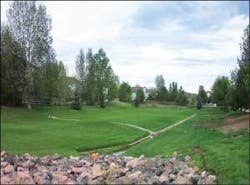
Figure 1. Detention Basin
In 1983, an EPA study revealed that the practice of stormwater detention could control the flood peak flow rates, but manmade drainage systems increased surface erosion and transported shock loads of chemicals and pollutants into natural streams in urbanized areas. In response to the needs of water quality control, the design of detention basins in the 1980s evolved to include a permanent pool that could capture frequent runoff events for pollutant control. The outlet structure was shaped by a high-flow outlet for the 100-year release, a low-flow outlet for the 10-year release, and a perforated plate or riser for daily runoff (ASCE 1992). Stormwater infiltrating and filtering devices were also added to the detention basin system to remove solids through the sedimentation process.
In the 1990s, further studies on stormwater detention indicated that extended release from the upstream detention had increased the duration and frequency of high flows to the downstream streams (Booth and Jackson, 1997). The downstream streams became unstable because of prolonged bank saturation and erosion. In response to the needs of natural stream habitats, the concept of on-site source control was introduced to stormwater management in the last decade.
Low impact development (LID) was developed to mimic the predevelopment watershed regime as the ultimate goal (EPA, 2006). Bioretention and porous pavement were the major devices to reduce the on-site runoff quantity, to improve the runoff quality, and to delay the flow time. Today, stormwater best management practices (BMPs) demand any and all drainage designs to reach the maximum probable extent that copes with the full spectrum of flood flows, mitigates urban stormwater issues, and balances the water- shed regime.
Types of Detention Basins
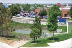
According to function, detention basins can be classified into two major categories: flood control detention basins (DB), and stormwater quality control basins (WQCB). A flood control detention basin temporarily stores excess storm runoff and then discharges it at a rate not to exceed the downstream channel capacity (see Fig. 1). Often, a DB is designed as a regional facility that provides the 100-year runoff storage volume at the outfall point of the developed watershed. Between events, a DB remains dry. Conversely, a retention basin (RB) has a permanent water pool (see Fig. 2). The solids and pollutants in stormwater can mostly be removed by the settlement process in the pool. An RB is often designed as a local stormwater control facility and placed at the source of pollutants, such as the outfall point of a residential subdivision or business district.
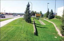
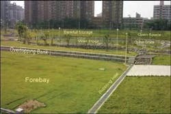
A WQCB is usually designed to be an on-site stormwater quality enhancement facility that is often located at the outlet of a parking lot, business pavement, or highway intersection (see Fig. 3). A WQCB consists of a very small storage volume, landscaping vegetation, highly porous bottom, and perforated plate or riser outlet. The basin is sized for the approximate flush volume of the 3-month event. Depending on the local subsurface and groundwater condition, a DB can be an all-in-one (see Fig. 4) that has a permanent pool (RB) with an infiltration/filtering bottom (WQCB). When the permanent pool in a DB can be sustained with a water depth greater than 6 inches, a wetland is formed.
Design Considerations
Basin Location
Under the concept of multiple land uses, DB sites can include parking lots, parks, sport fields, road embankments, on-site depressed areas, floodplains, drainage channels, swales, roof tops, and underground storage. Site selection depends on costs, public safety and maintenance. Specialists and engineers have to work together to develop desirable and acceptable criteria that fit the local community’s recreational needs as well as flood control purposes.
Figure 4. All-in-one Basin
Basic Layout
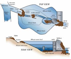
As illustrated in Figure 5, a DB comprises several components, including: inlet work protected by an energy dissipater; fore bay to act as a sediment trap; trickle channel to pass nuisance to low flows; multiple layers to form the required storage volume; outlet work to meet the allowable release rates; and an emergency spillway. All inlets should be protected by a trash rack or steel grate for debris control and safety.
At the DB entrance, the fore bay is equipped with a sediment baffle system and maintenance access for future cleanup. The fore bay storage volume is determined by the first flush runoff volume such as 0.25 to 0.5 inch per watershed area. The trickle channel through the bottom of the DB should have sufficient capacity to pass 30 to 50% of the 2-year peak flood flow or 1.0 to 3.0 % of the 100-year peak discharge. Gradient control or a drop structure can be installed to stabilize the trickle channel.
It is preferable that the DB width-to-length ratio be greater than two so that the flow can be expanded and diffused into the water body to enhance the sedimentation process. The performance of the DB outlet is dominated by the upstream headwater and downstream tailwater conditions. Selection of design coefficients, such as orifice coefficient, must reflect the actual DB operation in the future. The performance of the outfall culverts must be evaluated under both inlet and outlet conditions. Inlets and outlets must be protected from erosion and deposition of sediments. The slopes on the basin embankments have to satisfy the soil stability. As a rule of thumb, slopes on earthen embankments should not be steeper than 1V:4H, and on riprap embankments should not be steeper than 1V:3H (Guo, 2006).
Design Event
Flood control structures are often designed for multiple events. In general, a DB should provide a storage volume to reduce the 10-year and 100-year release rates. A freeboard of 6 to 12 inches is required. The emergency spillway for a DB should be able to pass the maximum probable runoff. If the DB is equipped with a WQCB on the bottom, the WQCB should be sized for a runoff capture rate of 80%, which implies that on a long-term average, 80% of runoff events generated from the tributary watershed can be captured by the WQCB without any overtopping or bypass flow. The stored water volume is considered treated by the settling process in the permanent pool over 12- to 24-hour drain time (Guo and Urbonas, 1996 and 2002).
Allowable Release Rate
Public safety is always the major concern in determining the release rate from a developed waterway. The allowable release rate from a DB is set to be the smallest among the following criteria:
Figure 5. Example Layout of Detention Basin
- historical (undeveloped) release rates;
- capacity of the downstream existing waterway;
- local drainage design criteria, such as approximately one CFS per acre recommended for the Denver metropolitan areas (USWDCM, 2001).
Surface Water and Groundwater
When the DB is operated like a dry pond for playground use, it is necessary to assure that the average time interval between storms allows the basin area to dry up. On the contrary, if the DB is designed to have a permanent pool, it is necessary to carefully evaluate the water budget among groundwater, surface water, and hydrologic losses. To design a DB without an outlet, the soil infiltration rate on the surface and the seepage rate under the surface must be carefully investigated. An overestimated soil infiltrating rate will cause groundwater mounting and back up the subsurface flows (Guo, 2001). Vertical drainage wells filled with coarse gravel are recommended to increase the infiltration rate.
For free downloadable computer software and Excel computing spread sheets for stormwater detention and retention system designs, visit www.udfcd.org.uwm
About the Author:
James C.Y. Guo, PhD and P.E., is a Professor in the department of civil engineering at the University of Colorado-Denver/HSC. More information on Dr. Guo and his research can be found at http://carbon.cudenver.edu/~jguo/index.html.
References
- American Society of Civil Engineers (ASCE). “Design and Construction of Urban Stormwater Management Systems,” Engineering Practice No. 77. New York (1992).
- Booth, D.B., and C.J. Jackson. “Urbanization of Aquatic Systems-Degradation Thresholds, Stormwater Detention, and the Limits of Mitigation,” Water Resources Bulletin, Vol. 33, pp. 1077-1090 (1997).
- Environmental Protection Agency (EPA). “Results of the Nationwide Urban Runoff Program,” EPA Final Report, NTIS No. PB84-185545, Washington, DC (1983).
- EPA. “Methodology for Analysis of Detention Basins for Control of Urban Runoff Quality,” EPA440/5-87-001 (September 1986).
- EPA. “Low-Impact Development Design Strategies: An Integrated Design Approach,” (2006). See http://www.epa.gov.
- Mays, L.W. Stormwater Collection Systems Design Handbook, McGraw-Hill Book Company, New York (2001).
- Jones, J., James C.Y. Guo, and B. Urbonas. “Safety on Detention and Retention Pond Designs,” Journal of Storm Water (2006).
- Guo, James C.Y. Urban Hydrology and Hydraulic Designs, Water Resources Publications, Littleton, Colorado (2006).
- Guo, James C.Y. “Hydrology-Based Approach to Storm Water Detention Design Using New Routing Schemes,” ASCE Journal of Hydrologic Engineering, Vol. 9, No. 4 (2004).
- Guo, James C.Y. and B. Urbonas. “Runoff Capture and Delivery Curves for Storm Water Quality Control Designs,” ASCE Journal of Water Resources Planning and Management, Vol. 128, No. 3 (2002).
- Guo, James C.Y. “Design of Circular Infiltration Basin Under Water Mounding Effects,” ASCE J. of Water Resources Planning and Management, Vol. 127, No. 1 (2001).
- Guo, James C.Y. “Detention Basin Sizing for Small Urban Catchments,” ASCE J. of Water Resources Planning and Management, Vol. 125, No. 6 (1999).
- Guo, James C.Y. and B. Urbonas. “Maximized Detention Volume Determined by Runoff Capture Rate,” ASCE J. of Water Resources Planning and Management, Vol. 122, No. 1 (1996).
- USWDCM. Urban Stormwater Drainage Criteria Design Manual, Urban Drainage and Flood Control District, Denver, Colorado (2001)
