Latest Pneumatic Actuator Developments
By Hubert Ferragne
A cornerstone of water demand management control, valves themselves are controlled by actuators. Here, we look at the latest developments in the field.
These days, operators tend to look increasingly if and how a valve will fit into their plant process control system before deciding which valve to buy. The operators of complex installations, for example for water treatment or for chemical and petrochemical production, are putting more and more pressure on the makers of valves to develop intelligent, micro-controller-fitted actuators capable of communicating by means of bus systems as well as with their environment.
State of the market
Part-turn pneumatic actuators presently are the generally accepted actuator type for this kind of application involving 90°-valves, e.g., ball or taper plug valves, and swing-type butterfly valves. Compressed-air operated actuators are inexpensive to make because of a very simple mechanical design. They’re suitable for use under explosive or humid ambient conditions. Even leakage won’t pose a health hazard for operating personnel.
Pneumatic actuators can either be triggered by a solenoid valve or operated with a so-called positioner. With the former, the actuator can only be set to the “OPEN” or CLOSED” positions. But, if settings between these two limit positions are required — for example, for throttling — a positioner is used. It converts an electric (4-20 mA) or pneumatic input signal (0-1 bar) from the control station to a pressure difference at the actuator piston which will persist until the valve has the desired opening angle. The positioner is, therefore, suitable for selecting any opening angle.
The main drawback of these devices is their complex design, which makes them expensive and sensitive to dirt. They also require compressed air even if the valve isn’t moving at all (assuming the operation concept involves a nozzle and a baffle plate).
The basic functions of automated valve control devices also include the feedback signal indicating that limit positions (OPEN/CLOSED) are reached or the continuous monitoring of the disc opening angle. To provide these features, it used to be common practice to fit the devices with mechanical or contact-free switches or a potentiometer. While the various components were for the most part of standard design, linking the parts tended to be a complex and costly affair. As they were normally made by a score of different manufacturers, it wasn’t always easy to assemble the devices and get them to work.
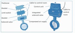
The current trend is to integrate all components into a single control unit that’s then connected to the automation system by means of a supply line (compressed air) and a control cable. With this arrangement, the (OPEN/CLOSED) or the infinitely variable setting of the actuator is controlled by an electronic card. This triggers redirection of the compressed air via an integrated valve and is also capable of performing other aforementioned operations. This solution is compact, easy to adjust, reasonably priced and it’s supplied from a single source. If required, the units can be supplied with additional sensors for leak detection or for measuring valve stem forces. These features help to check and assess the correct operation and condition of the valve from the outside.
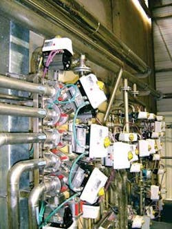
A fully integrated solution and arrangement consisting of separate accessories mounted on top of each other are compared in Figure 1. An Amtronic control unit used for valve automation has two cables attached to it; one to feed it with compressed air, the other — a control cable — to connect it with the automation system. By fitting the industrial valve with the necessary instrumentation, the manufacturer paves the way for a fieldbus network.
Fieldbus networks
Fieldbus networks have now been in use for several years to enable a number of devices “in the field” to communicate with a monitoring computer or PLC. This reduces the number of cables needed in an installation and shortens the time required to connect the actuators. The data required for control and the power supply pass through a single supply cable, which connects actuators, sensors and the process control processor to each other.
Network solution options
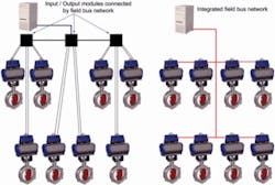
Two different solutions involving fieldbus networks:
- All control signals, be they analog or digital, are transmitted to the various Input/Output (I/O) modules. Communica¬tion between the I/O modules is digital. With respect to cabling of actuators and sensor, the arrangement hardly means a cut in expenditure since the number of cables and time needed to mount them are roughly the same.
- Actuators with an integrated fieldbus consist of a single cable linking all components. In this arrangement, the fieldbus network offers great advantages, because it allows all sensors and actuators to communicate with each other by means of a direct link. This greatly reduces the number of cables neededs. Modern integrated fieldbus networks have a modular structure, so existing protocols can be simply changed from one fieldbus standard to another by a change of communication card. And components are suitable for universal use.
Enhanced mechanical solutions
Christol Grease, a Shell subsidiary in Niort, France, has experienced the benefits of a fieldbus network since 1997. Its control units are interconnected by a single cable used by the valves to communicate and exchange information supplied by the control and travel stop signals. This integrated solution cuts the need for a central control unit as each control unit is directly linked to the process control processor.
As a result of integrating a programmable micro-controller, actuators are now capable of performing the monitoring and optimisation functions of valve control systems, which usually had to be initiated centrally — from a control panel or room, or manually — at the actuator itself. For example, if one wanted to slow down the actuation period of pneumatic valves in the past, this could only be done by throttling the inbound or outbound flow of compressed air. That meant two additional components had to be installed.
The desired closing or opening time had to be determined empirically by the tedious, time-consuming process of adjusting and readjusting a number of screws.
Adjustability of the time-dependent closing curve of the valve can also be used as a means of avoiding surge pressures called water hammer. The closing curve can even be used to respond to changes in the operating conditions of the installation, for example to fluctuations of supply pressure or ambient temperature.
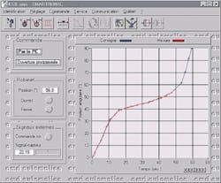
By programming the micro-controller integrated in the control unit, the operator can plot a curve from the PC. A system of coordinates representing the actuation time and closing angle simplifies plotting of the valve actuation curve as a function of time. The operator can monitor the valve disc motion on the display, with the required-values curve shown in blue, the actual-values curve in red (see Figure 3).
This simplifies automation. A digital signal controls the programmed valve which features integrated control devices for controlling its own functions. This is of particular advantage where long pipelines are installed and risk of surge water hammer is high.
null
Tank level control
As an example, the desired water level in a tank is maintained by programming the control unit in the valve actuator. The sensor used to measure the water level can be directly linked to the control unit. The set value is continuously compared with the actual value measured by the control system integrated in the switch box. This simplifies automation, because commands are carried out by the valve control unit directly. By means of the connected bus system, of course, the actuator also can be controlled from the central processor at any time. And water demand can be managed more efficiently and cost effectively.
Author’s Note:
Dipl. Ing. Hubert Ferragne worked formerly in automation products for KSB S.A.S. France, a unit of KSB AG, a leading producer of pumps, valves and related systems worldwide based in Frankenthal, Germany. Contact: Antoine Casteleyn, +33 (0)6 2605 5709 or www.ksb.fr
