Identifying and remedying problems in reverse osmosis processes
Reverse osmosis membranes are now commonly used for water purification. This article looks at how operators should deal with operational challenges such as falling rejection and a reduction in performance.
By Dr Jens Lipnizki
Reverse osmosis is a standard water treatment technology that has steadily gained increasing acceptance over the years. Handy design programs, helpful literature and improved knowledge have led to this technology becoming much more commonplace. As a result, reverse osmosis is no longer limited to use in industrial water treatment facilities but also now has domestic applications such as for treating mains water.
Whatever the application, however, the fundamental problems that can be observed in membrane processes have not changed, namely:
- Falling rejection
- Reduction in performance (reduced flow or higher pressure).
When such problems occur, the first question to be clarified is whether there have been any changes in water quality or temperature. To make it easier to localise problems, it is important to document basic parameters such as temperature, flow, pressure, yield and conductivity. In addition, it is also helpful to measure the pressure loss, preferably between the concentrate levels.
These data should be normalised, i.e. expressed in relation to a standard situation so that it is possible to assess whether the change in performance is due to the system or changed inflow parameters. Calculation tables for this purpose are provided by the membrane manufacturers free of charge. Aside from this, it is vital to check that other facility components such as measuring equipment, antiscalant dispensing units and ion exchange systems are running smoothly.
If after normalisation the data deviates as follows, the reason for this deviation should be investigated more closely.
- 20% higher salt passage (definition: salt passage = 100% rejection [%])
- 10% reduction in flow
- 20+% of pressure loss along a pressure pipe.
Frequently, small facilities only record a few measurement values, and these are generally not normalised. Where this is the case, the influence of temperature and variations in the salt load in the water should be taken into account. The rule of thumb here is that for each degree Celsius the temperature drops, flow is reduced by approx. 3%.
Investigating the problem
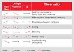
It goes without saying that the investigation process depends on the problem observed. If the salt passage has increased, i.e. the rejection has worsened, this can indicate chemical or mechanical damage to the membrane or element. Reduced flow, on the other hand, is generally due to organic, biological or inorganic fouling. It is difficult, however, to localise and then deal with the problematic point in the system.
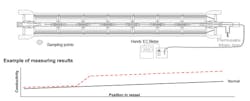
When there is increased flow and a deterioration of the salt rejection, the conductivity of the permeate in all pressure pipes is checked in case any of the values are significantly elevated.
If any single pipe is conspicuous, the element can be identified using the “central pipe testing method.” This involves passing a flexible hose into the central pipe of the coiling element to the end of the pressure pipe and then slowly pulling it back out, catching some of the permeate in the hose. This sample can then be tested for conductivity. Should this suddenly rise at any point, the location of the leak can be identified based on the length of hose that has been pulled out. The leak might either be due to damage to the element itself or to the interconnector between the elements.
If all the elements demonstrate significantly increased conductivity with higher flow, this could indicate permanent damage. This can be a result of oxidation agents such as chlorine, solvents that have dissolved some of the polymer membrane, or can be caused by overpressure in the permeate, which causes delamination of the membrane.
The upstream elements are more likely to be affected by oxidation than the downstream ones. Delamination, on the other hand, is more likely to affect the downstream elements, since this is where permeate overpressure is likely to be highest. Final clarification in this case can only come through an element autopsy, as this kind of damage cannot be assessed from the outside.
Increased flow and reduced rejection are clear indicators of a leak in the system that has to be remedied. This can frequently only be achieved by replacing the elements or small parts (e.g. O-rings, interconnectors).
Reduced flow
If there is reduced flow, or if greater pressure is required, there is soiling (fouling). Depending on how pronounced it is, this can also lead to a reduction in salt rejection. Fouling is often associated with increased pressure loss along the entire pressure pipe, as the flow channels become blocked.
While organic fouling primarily leads to blockages on the upstream side, the higher salt load on the downstream side is more likely to cause salt precipitation, i.e. inorganic fouling, or scaling. Biological fouling can spread throughout the entire system and can therefore be found at various points.
It is generally possible to determine the nature of the fouling by opening the pressure pipe. A quick inspection is usually enough to find an organic blockage, white salt crystals or biomass.
Uninstalling and weighing the element will determine the degree of fouling. It must be drained for approx. 15 minutes before determining the weight. If, for example, an 8-inch element that normally weighs approx. 16 kg suddenly weighs more than 17 kg, this could be due to heavy fouling. In most cases, cleaning the element in good time can restore performance. Alkaline cleaning should be used to clear organic or biological fouling, while complexing agents are used for inorganic fouling in acidic ranges.
Summary
A significant increase in flow combined with a simultaneous reduction in rejection must always be assessed as critical, as it can be attributable to damaged elements or seals. It is generally necessary to replace the damaged parts.
Decreased flow is usually caused by fouling. In this case, it is essential to determine the degree and nature of the fouling so as to select the appropriate cleaning strategy.
This can be conducted at appropriate institutions such as the IWW Water Centre (Rheinisch-Westfälisches Institut für Wasserforschung gemeinnützige GmbH) in Mülheim a.d. Ruhr, and involves both a test of the element and a surface analysis.
Ultimately, however, it is important to test whether the cause of the drop in performance can be eliminated so as to ensure a stable process.
Dr Jens Lipnizki is head of technical marketing membranes, Liquid Purification Technologies business unit for LANXESS Deutschland GmbH.
More Water & WasteWater International Archives Issue Articles


