By Mike Reeves, Mark Lewy
Groundwater infiltration modelling helps evaluate sustainable urban drainage options for wastewater planning and operational analyses.
SUDs is usually a less expensive solution than new stormwater infrastructure.
Sustainable Urban Drainage (SUD) systems, such as permeable pavements and ponds, are reducing the volumes of direct urban runoff, and helping to resolve problems such as flooding and pollutant spills to rivers in many countries, including Australia, throughout Europe and the USA.
Until recently, wastewater modelling packages could not model runoff and groundwater infiltration characteristics of SUD systems, so that modelling - an important tool in all wastewater planning and operational analysis - could not properly evaluate these important development options. However, new mechanisms in models can now represent the long attenuated runoff and variable loss to groundwater that until recently numerical modellers have struggled to replicate. One modelling approach, developed by Wallingford Software for the three main hydrological processes that occur in SUD systems, is implemented within InfoWorks CS, which is applied worldwide.
The three hydrological processes are:
- Highly attenuated runoff, as experienced with permeable pavements;
- Exfiltration - allowing water to be lost to the ground via structures such as soakaways and French drains;
- Rainfall runoff lost to infiltration at a constant rate, which occurs with structures such as ponds and swales.
Water engineers are increasingly turning to SUD systems to harness and enhance natural characteristics of an urban catchment in order to achieve hydraulic or water quality objectives whilst minimising the disruption to and alteration of the environment. Almost all SUD systems provide an element of storage that is used during periods of rainfall. Retained flow is either gradually released back into the natural watercourse or sewerage system, or allowed to infiltrate into surrounding ground. SUD systems can be used to filter out pollutants.
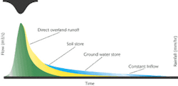
Figure 1. Groundwater infiltration
SUD solutions are used in preference to more traditional methods such as building large storage tanks. In addition to environmental benefits, SUD systems are often the lower cost investment option.
Highly attenuated runoff
Highly attenuated runoff occurs in such SUD systems as permeable pavements, which are most commonly used in car parks. Other sources of highly attenuated runoff include stream ingress or contributions from large permeable areas.
Two main processes occur when rainfall lands on a permeable pavement. It can run directly over the surface of the pavement and into the nearest manhole, or it can sink through the pavement and enter the sub-base. Once in the sub-base, it enters the sewer as attenuated runoff or sinks into the soil and provides no contribution. A wide variety of these types of pavements exist and one or more of these processes are excluded in many of them. For example, in some types no mechanism allows either direct runoff or return of flow from the sub-base to the sewerage system.
Direct (overland) runoff has three components:
- Initial losses - the first few milli-metres of rainfall landing on a catch-ment provide no runoff contribution. They are lost due to processes such as catchment wetting, settling of dust and cooling of the catchment surface.
- Runoff volume - the proportion of rainfall landing on the catchment surface which runs off into the sewerage system.
- Runoff routing - the speed of runoff, or the time taken to enter the sewerage system.
The processes occurring once flow enters the sub-base are described by a separate utility in the model, called the groundwater infiltration model.
Groundwater infiltration modelling
Existing infiltration models are generally of two types, empirical or deterministic. The simplest empirical infiltration models involve fitting a sine curve to infiltration measurements. More sophisticated empirical models use separate regression curves for the different components of infiltration such as dry weather infiltration and rainfall induced infiltration.
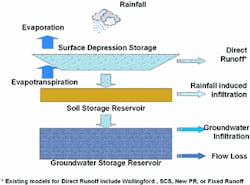
Figure 2. Soil and groundwater storage reservoirs
The groundwater infiltration model described here is deterministic and takes account of antecedent hydrological conditions. Deterministic models use bulk mass balance equations and simplified flow equations to approximate the physical processes, and rely on some degree of calibration because of the large computational overhead of modelling the below surface processes. The input from a subcatchment to the groundwater model is any rainfall left over from direct overland runoff.
The model is represented by two linear reservoirs, one representing a soil component (the soil storage reservoir) and the other a groundwater component (the groundwater storage reservoir). Figure 1 illustrates the interaction of these reservoirs with overland runoff. Figure 2 shows the sewerage system response from the direct overland flow reservoir and two groundwater reservoirs.
Any runoff that enters the groundwater infiltration model, first enters the soil storage reservoir. The amount by which the level in the reservoir rises is a function of the soil porosity. For example if 1 mm of runoff enters the reservoir and the porosity is 30%, then the level rise in the reservoir is 3.33 mm. Once the level in the reservoir exceeds a defined level, called the percolation threshold, it will provide a contribution. This contribution can go either directly into the pipe, or percolate down into the groundwater storage reservoir. A simple percentage defines the relative amounts that enter the pipe and groundwater storage reservoir. The speed (often thought of as the delay) of the flow entering the pipes is defined by a routing coefficient. During periods of dry weather the soil storage reservoir will empty through a process of evapotranspiration at a defined rate.
The groundwater storage reservoir acts in a similar way to the soil storage reservoir, as again the rise in the level of the reservoir is a function of the defined porosity. The difference is that here there are two defined thresholds. The infiltration threshold defines the level at which there is a contribution to the pipe and the base flow threshold defines the level at which there is a loss to the surrounding soil from which there can be no contribution.
Below ground SUD systems - exfiltration
Below ground SUD systems loose flow to the surrounding soil. This type of structure includes soakaways and French drains. The rate of loss is a function of several parameters, including the base area and height of the structure and porosity of its fill material.
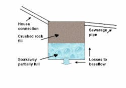
A soakaway, common for example in the UK, is a shallow trench filled with coarse gravel, surrounding a property, in which water is collected either via guttering, or direct runoff from the roofs. The soakaway fills up and eventually discharges (overflows) to the sewerage system. The soakaway, shown in Figure 3, also drains to the surrounding soil, through the base and sides.
Figure 3. Soakaway
A French drain looks like an infiltration trench, but with a pipe running its length. It could be modelled in a similar way to a soakaway. The rate at which the drain fills is a function of porosity. Once the water level exceeds the pipe invert level (which can be at the base of the drain), water will start to flow into the pipe.
Above ground SUD systems
Ponds and swales typify above ground SUD systems. They provide storage, which once filled, contributes to the sewerage system or water course. The contribution is a function of continuing rainfall. Losses to the soil are assumed to occur at a constant rate. During periods of dry weather, these structures can empty, thus providing a volume of storage for the next rainfall event.
Conclusion
SUD systems have not been easy to represent in models to date, but this has now changed. The main work now is to further use these new mechanisms in models for calibration against real world situations and then to apply them to the design of SUD systems.
Authors' note
Mike Reeves is the senior support engineer for Urban Drainage at Wallingford Software, based in Wallingford, UK. Mark Lewy is the senior developer at Wallingford Software.


