Increasing numbers of Coal-to-Chemical facilities in China, driven by strict regulations on wastewater discharge, mean Zero Liquid Discharge technologies are becoming a popular choice. Ajanta Sarkar details an installation of advanced, hybrid ZLD and reverse osmosis processes to help treat major contaminants, as well as sludge in a solar pond.
The recent boom in coal-to-chemicals conversion in China will likely have significant impact on global chemical manufacturers. China is actively encouraging the growth of coal-to-chemicals in a bid to reduce its dependence on expensive imported natural gas. Testament to this shift, reports show that the country has built around 20 coal conversion plants over the past two years.
However, with ecological conservation and environment preservation becoming more important than ever, governments across continents are mounting pressure on industries to achieve environmental compliance. In China, too, industries are strictly prohibited from discharging ecologically hazardous waste originating from their facilities. Regulations are also becoming progressively strict on industrial wastewater discharge.
As a result, Zero Liquid Discharge (ZLD) technologies are increasingly being explored as an alternative wastewater management strategy to reduce environmental impact.
In fact, the community of coal-to-chemical industries in China has decided to implement ZLD in most of the production facilities.
ZLD solutions may be based on standalone thermal/evaporative processes, membrane processes, or a combination (hybrid) of the two. An example of such a hybrid approach is a recent project under commissioning in China's coal-to-chemical industry.
Project details
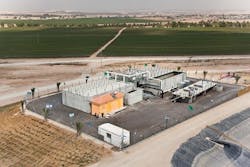
The following project outline is based around a coal-to-chemical facility located in China's Inner Mongolia province, awarded in January 2010. As an environmentally conscious corporate entity, the firm opted to become a ZLD facility. The program is used to treat multiple waste streams with major contaminants such as oil and grease, volatile organic compounds, and high dissolved solids levels with potentially high variation in constituents from the facility to ZLD. The main sources of these contaminants are from the raw water reverse osmosis (RO) plant and the cooling tower blowdown streams. These effluents are first mixed in an equalization tank before further treatment.
Combined wastewater is rich in contaminants like oil and grease, volatile organic compounds, and has a relatively high Chemical Oxygen Demand (COD) and Total Dissolved Solids (TDS) of about 16000 mg/l.
As indicated in the design analysis shown in Table 1, the facility's composite effluent water has a high fouling and scaling tendency. Total water to be treated amounts to 110 m3/hr and the only waste allowed from the plant is solid waste in the form of sludge and salt slurry into a solar pond. Due to the high fouling potential, the water is difficult to treat and hence the need for technology evaluation before selection.
Technology evaluation
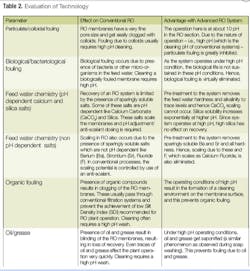
Since the RO technology is affected by many difficult contaminants in water, a need to evaluate an advanced RO technology was imperative. The project team decided to evaluate the patented High Efficiency Reverse Osmosis (HERO™), an advanced RO process for this application with respect to a conventional RO process. Based on the parameters and advantages highlighted in Table 2, the HERO was found to be the most suitable technology.
Using the selected technology, the reverse osmosis section is operated in a high pH environment. Due to this, the major parameters affecting RO system operation are kept within limits, enabling high recoveries in the reverse osmosis membrane system, limited only by the osmotic pressure of the reject. In this case, the design recovery is in the range of 80 – 85%. Since the requirement was for a ZLD plant, the RO system was also being used to concentrate the dissolved solids in its reject stream and reduce the total capacity of the ZLD plant by having high recoveries across the RO.
A steam-driven brine concentrator (BC) based ZLD system was provided. The small stream of salt slurry from the BC is taken to the solar pond to achieve the ZLD mandate.
Process details
The process scheme involved a number of steps including:
• Clarification: The mixed effluent is passed through a clarification system. This unit is used for the removal of hardness by lime soda softening process. Coagulants and other chemicals are injected for better efficiency. In order to maintain ZLD, all waste streams internally generated within the plant are recycled upstream of this clarifier.
• Sludge Handling: sludge produced in this unit is mainly CaCO3 and Mg(OH)2 and is further de-watered by a centrifuge to extract water from the solid waste before disposal. Water coming from the centrifuge is recycled back upstream of the clarifier. Solid cake is then disposed in landfill.
• Filtration: clarified water from the clarifier is then filtered for removal of residual suspended matter to < 2.0 NTU. Media in these filters consists of anthracite and sand.
• Pre-treatment - softening: filtered water is then softened to very low levels of hardness. The softening is carried out in two stages. In the first stage, sodium zeolite softener units are used to remove most of the hardness. Regeneration of these softening units is done with brine.
• This is followed by Weak Acid Cation Exchanger (WAC) resin in Na form in the second stage of the softening process. Here the hardness-causing ions are removed to very low levels of < 1.0 ppm. These units are periodically regenerated as required, followed by a de-gasser tower for removing the residual alkalinity. The above process results in the production of water with a very low scaling potential. The next stage is the RO Block: preconditioned water is passed through cartridge filters, followed by the advanced reverse osmosis equipment operating at high pH. This system operates at very high recovery of about 80 - 85%. It removes the dissolved impurities from the stream and produces a permeate stream of lower TDS and a reject stream of higher TDS.
• Since all other waste streams in the plant are recycled upstream of the clarifier, the feed to the ZLD is only the high TDS waste in the form of RO reject. This limits the size of the ZLD plant, which is economical in capital as well as operating costs. Most importantly, the feed to the BC is free of all hardness and common scalants, ensuring lower down time in maintenance and cleaning of the BC.
• Brine Concentrator based ZLD System: reject at high pH from the reverse osmosis units is pre-heated by exchanging heat with the outgoing hot distillate in a heat exchanger. Pre-heated feed is sprayed into the de-aerator where the non condensable gases like carbon dioxide and oxygen are removed and vented. This minimises corrosion in the system.
• The feed then flows to the falling film evaporator. The feed is mixed with the brine and circulates over the tube surface. Water in the brine is converted into steam by absorbing the latent heat in the compressor discharge. Brine is discharged from the system to maintain the concentration in the evaporator system.
• Vapor flows through a mist eliminator that removes entrained droplets of brine from the vapor before it flows to the vapor compressor. The compressor increases the vapor saturation pressure and temperature so it can be used as heating steam in the evaporator. Compressed vapor transfers its latent heat to the brine circulating on the inside of the tubes. This generates vapor to be feed to the compressor, which is condensed on the outside of the tubes and the condensed vapor (distillate) is pumped through the feed distillate heat exchanger and out of the system.
• The brine concentrator is designed with a very low temperature difference between the heating medium and the boiling brine and a high recirculation rate. The two main benefits are reduced scaling rate and a lower steam requirement. Energy efficiency is maximised by utilizing outgoing distillate and vent steam to preheat the incoming feed. Brine is concentrated to approximately 18-24% total solids in the evaporator to achieve very high recovery factor. Blowdown from the BC flows to the solar pond. The permeate from the RO and the distillate are mixed and used as cooling tower make-up water.
Configuration benefits and conclusion
Where advanced RO and ZLD technology are combined, numerous advantages can be achieved. Firstly, there is no Silt Density Index (SDI) Limitation. As SDI is not a limiting factor in this mode of RO operation, expensive upstream units such as microfiltration/ultrafiltration systems are not required, thereby reducing system capital costs.
Furthermore, no propriety chemicals are required. Technology is based on adjusting the RO operating conditions to ensure lower scaling tendency of the water. Hence, expensive proprietary anti-scalants and cleaning chemicals are not required. Also, as the RO system allows higher water recovery, the cost per unit of pure water produced is lower than comparable processes. Equipment size is often an important factor taken into consideration by plant owners and operators. In this example, higher recovery in the RO system means lower concentrate flows and hence, smaller size for the downstream ZLD equipment.
The plant is due for commissioning, now awaiting feed water generation from the upstream plant. The permeate generation is expected to reduce their raw water requirements substantially while eliminating the effluent disposal requirements. Hence, this plant is expected to have a positive impact in reducing both the carbon footprint as well as the water footprint. WWi
Author's note:Ajanta Sarkar is deputy general manager, process & application engineering for Aquatech Systems Asia (Pvt), a wholly owned subsidiary of Aquatech International Corporation. For more information please email: [email protected].
More Water & WasteWater International Current Issue Articles
More Water & WasteWater International Archives Issue Articles
