Standardized Tests Compare Sediment Retention Devices
By Marc S. Theisen and Kevin Spittle
One of the greatest problems facing specifiers in achieving NPDES sediment reduction goals is the lack of quantifiable criteria for the performance of Best Management Practices (BMPs). Standardized methods to quantify effectiveness of sediment reduction devices and stormwater treatment devices have only recently been proposed and are currently under consideration by ASTM.
Standardization Testing of Sediment Control BMPs
Available in the marketplace are numerous types of Sediment Retention Devices (SRDs), which may be considered a subset of Storm Water Treatment Devices (SWTDs). Examples of SRDs include silt fences, channel silt dikes, wattles, fiber rolls, compost socks and fiber filtration tubes. The lack of standardized evaluation procedures has led to unsatisfactory performance of SRDs and unexpected sediment runoff into streams and storm sewers.
An independent and well-documented large-scale testing procedure would assist the users of SRDs in establishing improved design and performance criteria. Owners, agencies and contractors would save money by installing the correct SRD for the required site controls. And, product manufacturers would have a clear, generally recognized methodology for establishing product capabilities.
Proposed Standard Test Method
In a proposed test method, sediment-laden water is allowed to flow up to and through an installed SRD. The measurement of sediment that passes through the SRD compared to the amount in the upstream flow is used to quantify the effectiveness of the SRD in retaining sediments.
SRD effectiveness is installation dependent and replication of field installation techniques is an important aspect of this test method. The test method is full-scale and, therefore, appropriate as an indication of product performance.
Apparatus
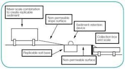
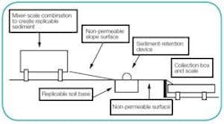
The test procedure requires a significant investment in related equipment to accomplish the full-scale testing of SRDs as shown in the testing system diagram (see Figure 1). The system includes the following components:
- A tank with an internal paddle mixer device mounted on scales capable of holding/weighing 10,000 lbs of sediment-laden water.
- A sufficient source of water and associated pumping equipment to repeatedly fill the mixing tank in a timely manner.
- A stockpile of soil in sufficient quantity to both create sediment-laden water and to create/replace subgrade in the installation zone.
- A front-end loader to dump a prescribed amount of soil into the mixing tank.
- A valve-controlled discharge hose that allows for controlled discharge from the mixing tank.
- Sampling jars (at least 12 per test) for taking “grab” samples periodically during the test.
- Earthmoving/compacting equipment to prepare/replace soil in the installation zone.
- A tank mounted on scales of sufficient volume to collect all runoff passing the SRD.
Retention Area
A non-permeable slope surface immediately below the mixer discharge should be provided to spread the initial discharge and to provide a retention zone above the installation zone. An installation zone about 5 feet wide by the width of the retention zone comprised of prepared soil subgrade should be provided to allow full-scale installation of the SRD to be tested. Because the prepared soil subgrade will be compromised, it will have to be reconstructed after each test. The area below the installation zone should be non-permeable to facilitate efficient transmission of runoff passing the SRD to the collection tank.
The Collection Area
The collection tank should be at a lower grade than the installation area so that runoff passing the SRD will efficiently flow via gravity into the tank.
Procedure
SRD Installation: Prepare the installation zone using the same soil to be used as sediment, unless otherwise agreed with the client. The soil shall be placed to a depth in excess of the depth of installation and compacted to greater than 90% standard Proctor. Install a representative sample of the SRD to be tested. The installation should extend beyond the width of the retention zone sufficiently to assure that runoff does not run around the ends.
Mixing, Releasing, and Collecting Sediment-Laden Runoff: Procure screened soil in adequate quantities for the testing procedure and determine its characteristics for future replication needs. Create sediment-laden runoff by combining water and soil in the mixing tank and maintaining agitation during the test. Create the sediment-laden runoff based on a 10-year, 6-hour storm event producing a 4-inch (100 mm) rainfall. A theoretical contributory area of 100 feet (30 m) slope length by 20 feet (6 m) wide was selected to limit runoff to sheet flow conditions. Additionally, the associated sediment load was calculated using the Modified Universal Soil Loss Equation (MUSLE) that allows for calculating a storm-specific quantity of sediment. Release the discharge evenly for 30 minutes, measure the quantity of released runoff at no less than 10 minute intervals by noting the reduction in weight in the mixing tank.
Take grab samples at 10-minute intervals from the outlet hose discharge. Additionally, as runoff passing the SRD enters the collection tank, record the weight and height of runoff in the collection tank, and take grab samples of runoff entering the tank, also at 10-minute intervals. Cutoff time is 90 minutes.
Data Collection: Select a specific upstream and downstream location for taking all grab samples. Collect all samples in the same size container and in the same manner. Pre-mark each container and do not overfill or overrun the sample bottle. Concentrations may be small, thus poor sampling techniques may significantly affect results. Multiple measurements cause a hectic pace, so pre-marking and recording immediately ensures consistency and accuracy.
Sediment-laden water in both the mixing and collection tanks is primarily measured by weight. Additionally, the height of the collected liquid in the collection tank is also recorded. Also, it is important to make and record visual observations relevant to the testing, such as height of ponding, undermining, overtopping, etc, as well as the associated times.
Lab Testing: Grab samples shall be evaluated in a lab to determine percent solids content. Vacuum filtration is recommended.
Calculations
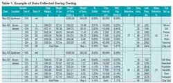
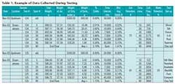
After recording all collected data in a table, noting the time of each sampling, calculate soil retention effectiveness by comparing the amount of soil loss during the test (solids passing the SRD) to the total amount of soil placed in the mixing tank (see Table 1).
Results: 2003-2004
In 2003 approximately 36 tests utilizing 2 different soil types were performed, observations taken and grab samples analyzed. In the summer and fall of 2004 additional research was conducted at the Stormwater Lab under the direction of PROFILE Products, LLC. The purpose was to duplicate and validate prior research and to evaluate other SRDs. Initially a prototype fiber filtration tube was researched to determine performance properties under varying installation techniques. Comparative results from 2003 and 2004 are shown in Table 2.
Subsequently a second round of testing was proposed to evaluate the benefits of more than one SRD installed in series, as would be common in steep slope or low flow ditch or channel applications. The 2003 research demonstrated the superiority of higher profile, well-installed devices, such as the sliced silt fence, for applications such as perimeter sediment control. Since this type of device is designed to maximize ponding height, its usage in higher flowing channels would not be recommended.
For steep slope and low flow channel applications, a series of lower profile devices may be more desirable. Although each individual device may not capture as much sediment as a higher profile device, theoretically there would be fewer problems associated with disruption of flow, undermining, water flowing around the device or ultimately the device being knocked over by the force of flowing water. In addition, the cumulative sediment capture of multiple low profile devices acting as “speed bumps” may actually exceed the sediment capture of fewer higher profile devices. In addition to sediment capture, other factors such as ease of installation, aesthetics, filtration, improvements in water quality and compatibility with complementary erosion and sediment control devices, should be considered.
Results: 2004
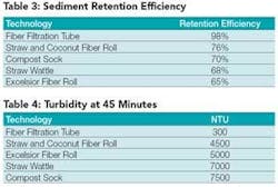
The SRDs evaluated demonstrated varying degrees of performance and sediment capture effectiveness. A summary of initial test results is presented in Tables 3 and 4.
The initial tests suggest that, under the chosen test conditions, the proposed test procedure established some relative effectiveness numbers to utilize for comparison. This information deduced several findings, including that the 2004 findings were consistent with those in the 2003 study that compared SRD technologies using only one installed device. In addition, the study found that the fiber filtration tubes provided significantly greater sediment retention efficiencies than the other SRD technologies evaluated. Only the fiber filtration tubes provided three-dimensional filtration, demonstrating complete saturation across the entire three-dimensional profile of the device. The fiber filtration tubes also provided much lower turbidity levels than the other technologies.
Acknowledgments
The research reported herein was supported by The Stormwater Lab, Ankeny, Iowa. Tom Carpenter and Joel Sprague provided invaluable guidance and direction on the research and testing protocol.
References
- Sprague, C. Joel and Thomas Carpenter. A New Procedure for Testing the Effectiveness of Sediment Retention Devices. Proceedings of 2004 IECA Conference, Philadelphia, PA (2004).
- Sprague, C. Joel and Thomas Carpenter. Testing the Effectiveness of Sediment Retention Devices under Standardized Runoff Conditions. Proceedings of 2004 Stormcon Conference, Palm Desert, CA (2004).
- Theisen, Marc S. and David A. Woelkers. A Proposed Classification of Current Manufactured Stormwater Treatment Best Management Practices. Proceedings of 2003 Stormcon Conference, San Antonio, TX (2003).
About the Authors:
Marc S. Theisen, M.S., CPESC is director of business development for PROFILE Products LLC. He has over 20 years of experience in the erosion and sediment control industry. He is a Certified Professional in Erosion and Sediment Control (CPESC), on the Board of Directors of the Erosion Control Technology Council (ECTC), and a long term member of the International Erosion Control Association (IECA). Theisen has authored numerous articles and technical papers on the development, testing, and application of erosion and sediment control materials.
Kevin Spittle is vice-president of research and development for PROFILE Products LLC. He has over 20 years of experience in the erosion and sediment control industry. Spittle is Chairman of the ASTM D-18.02.08 Section on Sediment Control, a member of the IECA, and a former Director of the ECTC. He has developed numerous erosion and sediment control products and holds several manufacturing and application patents.
