Practical Notes on Water Pump Piping
Improper flange alignment and excessive forces on nozzles are some of the causes of pipeline connection issues and leakages. The optimum piping design, support arrangement and piping layout/configuration at a facility cannot be underestimated. Amin Almasi discusses the latest achievements on water pump piping.
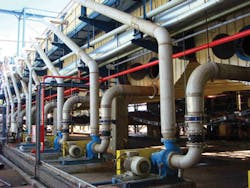
Water pump piping should have flexibility yet on the other hand, the support system (support members, attachments, others) should be designed to sufficiently support the water piping to minimize the loads on the water pump nozzles. Application of some common general plant piping practices could lead to real problems in the water pump piping systems, such as "too-flexible support system".
Nozzle Flange Connection
To minimize pump nozzle loads and facilitate the installation of water pump piping, the water pump nozzle flanges should be parallel to the plane shown on the water pump drawing to within a certain limit (usually 0.1 - 0.5 degree). The water pump flanged joints (the water pump nozzle flange and the piping flange) should correctly be connected for a trouble-free start-up and the subsequent operation. Several common causes of the flange connection issues and leakages are:
• Uneven bolt stress: Flanges which bolted up unevenly can cause some bolts to be relatively loose while others are heavily loaded (they could locally crushed the gasket)
• Improper flange alignment: Improper flange alignment could result in unevenly bolted joints, improper connection alignment, uneven compression of gasket, and often a leakage
• Improper cantering of gasket: Such a gasket will be unevenly compressed
• Dirty or damaged flange faces
• Excessive forces on the flange nozzles: This can occur because of improper piping flexibility design, improper location of temporary or permanent supports or by excessive application of force to attain flange alignments.
For a given bolt load, a narrower gasket will experience a greater unit load than a wide gasket. A common reason for a gasket leakage is the use of gaskets which are too narrow or too wide. It is therefore important to use a correct gasket with a proper width. The gasket thickness determines its compressibility and the load required to seat it.
The thicker the gasket, the lower the load necessary for seating. A proper thickness can assure a sufficient compressibility to accommodate slight facing irregularities while having a sufficiently high seating load to prevent blowout. A controlled torque bolt-up should be warranted for all water pump flange connections. For a stud larger than 20 mm, a proper hydraulic wrench should be used.
The bolting at operating conditions during the start-up (the initial period of operation runs) has been found to be an important factor in minimizing the flange connection problems. During the operation (because of the water pump operation and some temperature/pressure changes), the bolts and gaskets can deform permanently.
This could cause a loss of bolt stress. The bolting at operating condition can help to correct this effect, particularly to restore the original bolt stress which has dropped (or changed) due to yielding or creep of the flanged joint components. The bolting should start at the point of relatively peak of gap (or leakage, if any) and proceed in a crisscross pattern.
Temporary inlet strainer
It is very important to start-up any water pump with a clean piping, particularly on the suction of each stage. Any dirt, rust, welding beads, or scale which carried to a pump can cause serious problems. The piping should be fabricated with sufficient flange joints so that it can easily be dismantled for cleaning. It is far better to clean and test piping in sections before the erection.
When piping cleaned in sections, it may be possible to do a thorough job of eliminating all in-place cleaning. This is difficult to do with the piping in position because the water pump may be damaged. Even though the cleaning procedure has been carefully followed, a temporary strainer should be installed in the suction line of each water pump casing.
The provision should be made in the piping to check the pressure drop across the strainer and to remove the strainer element for cleaning.
Piping system vibration
One of the most obvious effects of the piping vibration or pulsation (particularly sustained vibrations) is fatigue failure, especially at critical high bending stress regions. The existence of such vibration suggests three approaches:
• Supply mechanical restraints to prevent movement of the piping system
• Eliminate or control the vibrations or pulsations (eliminate or decrease vibration at its source, the water pump)
• Eliminate the coupling of vibrations or pulsations as the forces into the piping system (eliminate the excitation, for example, change the natural frequency of system to avoid the resonance).
While each of these approaches is valuable, there is not simply one optimum solution for all cases of the water pump piping. Some of them could be excessively expensive, impossible, impractical or ineffective for a specific case. For example, the cost of mechanically restraining a large-size overhead water piping could be very high.
Despite the fact that many criteria have been evolved for the piping vibration or pulsation (from different point of views such as the noise, the safety, environmental, and others), in reality, it is not the vibration or pulsation amplitudes which are problematic, but rather the dynamic stress level in the piping system should be limited below the destructive levels. Whenever vibratory stress exceeds the endurance level of the piping, failure is imminent.
By this argument, any vibration amplitude criteria for water piping system should be applied very carefully. Special considerations should be given to the configuration of the piping system being studied. In other words, vibration amplitude criteria for a piping system should consider the piping configuration involved. The stress level in a piping is mainly a function of the physical distortion.
Obviously, the dynamic stress generated in a cantilever span due to a vibratory deflection is different than in that generated in another complex configuration by an equal vibratory deflection. A lower stress is generated in a long (straight) piping span that in a short complex one (such as "L" shape, "U" shape, loop shape, etc) as result of the same dynamic deflection.
An investigation into the dynamics of different piping configurations show that variation in dynamic stress per unit of vibratory deflection tracks rather directly with natural frequency of a given piping. For example, a long (straight) flexible span has relatively low stress and relatively low natural frequency. This natural frequency variation may be used advantageously to normalize allowable dynamic stress criteria (of course it is just an approximation).
Based on this approach, vibration velocity criteria could be specified for each piping configuration. In order to apply the vibration velocity criteria for a piping system, the stress concentration factor and other mechanical factors (such as corrections for concentrated weights, non-ideal end condition, changes in pipe diameter, and effects of vibration mode shapes) should be taken into considerations.
As a rule of thumb, the water piping vibration velocity limit can be mentioned as 7-12 mm/s and 3-8 mm/s for a long piping span and a short complex piping (such as "L" shape, "U" shape, loop shape, and others), respectively. It is just an indication and higher vibration values (compared to above-mentioned) may be acceptable depending on a case by case study.
Piping Support and Flexibility Study
Piping support systems are generally designed by two major rules:
• The support locations are determined by the guidance of the maximum allowable spans
• The support types are selected based on the expected operational displacement, dynamic situations, stress analysis and similar operational effects.
Flexibility studies (or piping stress analysis) are intended to verify that stresses in the piping as well as loads on the water pumps (forces and moments at on the water pump nozzles) are within the acceptable limits through all anticipated phases of normal and abnormal operation. All possible situations including installation, various operating conditions, start-up, normal shutdowns, emergency shutdowns, upsets, and others should be considered.
Piping of water pumps should be designed and supported so that the water pumps can be dismantled or removed without adding temporary supports (only with removing spool pieces).
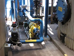
The water pump piping should be supported on integral extensions of the equipment support structure or independent structure (or support), and not be anchored to the water pump or its base-plate.
Notes on friction
For any piping systems which need to be supported at points where rigid-restrains are not permitted, special spring or flexible supports should be considered. Sometimes it is necessary to use support devices with high damping (such as snubbers or dampers). These supports could provide protection to the piping systems from different potential excitation sources such as mechanical induced excitation, pulsation, water flow excitation, pressure surge and hydraulic hammer, as well as seismic and other extreme dynamic loads. These snubbers or dampers are not only expensive but also require constant maintenance. They often have a built-in play that allows the restraint point to move a certain amount before being stopped.
Such slack makes the snubber (or the damper) a poor restrain for small amplitude steady state vibrations, particularly piping connected to the water pumps. A friction restraint may be more suitable for these cases. For example, by using frictional sway braces adjusted to suitable forces, the braces will acts as quasi-rigid stops during earthquake, dynamic or shock events, while accommodating proper operational movements.
This system, if properly applied, can help to improve water pump piping system natural frequencies, offers suitable frictional damping and resists steady state vibrations.
Author's note: Amin Almasi is lead rotating equipment engineer at WorleyParsons Services, Brisbane, Australia. For more information, email: [email protected].


