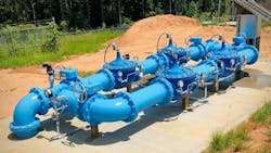
Control valves (CV) are found throughout municipal water distribution systems and are integral to maintaining consistent water pressure and supply. The importance and ubiquity of control valves underscore their significance in the functionality and reliability of water distribution infrastructures. To ensure the CV provides the functionality required with years of trouble-free operation, it’s important to select the correct size of valve and accessories, while providing a well-designed environment for the operational personnel that will have to maintain this valve.
Sizing your valve
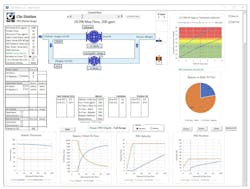
Most valve stations in municipal water situations are pressure reducing valves and selecting the right size is important, as problems can arise from incorrect sizing. Rather than sizing the valve based on line size, it is necessary to consider flow, pressure, and velocity. Knowing the size of the water main and the maximum, average, and minimum flow demands, one can move forward in the valve size selection. Some manufacturers, like Cla-Val, have a sizing software program that makes it quick and simple to size a valve correctly, but understanding what the program is considering is useful.
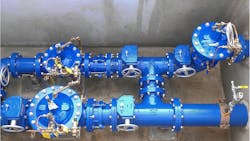
A software program will select a valve size based on the maximum required flow the valve has to pass, based on the minimum system differential pressure. This will be the upstream pressure minus the required downstream pressure that the reducing valve will be set at. The program will consider the velocity passing through the valve - it is best to limit this to 20 feet per second, (6 m/s) in valves operating continuously. In valve stations, it is common to have two control valves in parallel. The larger valve on the main line is designed to take care of peak flows, while the smaller second valve on a bypass will take care of low flows. Typically, the smaller, bypass valve will be sized to handle approximately 20% of the peak flow.
The smaller valve is also set slightly higher in pressure than the large valve. This allows the smaller valve to open first in the sequence, followed by the large valve as flow increases. The smaller valve is also the last to close as flow diminishes. This bypass line also offers redundancy as either of the valves can be used to supply the network while the other is being serviced. This is particularly important where it is not possible or practical to shut off the main water supply for periods of time.
Some manufacturers have software to support valve station design and allow engineers to consider the impact of velocities, among other things. Often, the velocity in a bypass valve can be excessive, potentially causing damage to the small valve and increasing loud noise levels. Using software a designer can specify the use of a transition device that will bring the main line valve into operation before high velocities are reached, which is often before the lower pressure setting of the larger valve.
Consider the risk of cavitation
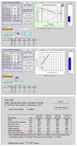
Anytime there is an application where reductions from a higher pressure to a lower pressure, and that ratio is greater than 3:1, there is a real risk of cavitation. This phenomenon will destroy a valve over time due to erosion and can create noise and vibration in the pipeline that may be a problem for nearby residents. However, unlike in days past when multiple valves would have to be installed to stagger the pressure drops, this can now be achieved through an anti-cavitation trim. This is a specific trim consisting of two stainless steel cages with slotted openings or drilled orifices, that contain the cavitation in the center of the cages, eliminating the disastrous erosion issues.
It is always recommended to run a cavitation software program to determine if cavitation will be a problem, and this should be a program specific to the manufacturer’s valve. Generic programs are available but do not account for the actual body shape of the valve.
Options to customize
The real advantage of diaphragm-actuated globe valves is that one can have a pilot system tailored to a specific application. Numerous features can be added to give a custom solution that provides real operational benefits.
Stainless steel pilot systems are popular and the price differences to brass/bronze or copper is not restrictive, and it should last longer, particularly in harsher environments. Pilot systems can be installed on either side of the control valve so give some thought to the location for accessibility with ladders and also clearance for maintenance. Pilot tubing is frequently stepped on or knocked because of poor placement - with a little forethought, this is avoidable.
The pilot system should always be installed with a strainer and can be a flow clean, internal style, or an external Y-strainer style. In tough applications, a water filter can be used. Pilot isolating valves are vital for maintenance and troubleshooting of the valve - even on the smallest of valve sizes.
Consider other options. A valve position indicator is very useful for operations personnel as it gives the ability to see the exact position of the valve during operation. If a remote signal is required this can be upgraded to a position transmitter, supplying a 4-20 mA signal via SCADA or a limit switch can be added to give an output for a position transmitter. Pressure transmitters can be added to give 4-20mA signals for both inlet and outlet pressures. This option is useful if the intention is to utilize a pressure management program in the future.
Also, consider options to give more system control. A second pilot control can be added to give the ability to have upstream pressure sustaining. This is very useful in situations where there is a need to protect the upstream from being starved of pressure by high downstream demand. If downstream surge could be an issue, a downstream surge pilot can be added to the reducing valve that will close the control valve quickly should the downstream pressure rise slightly above the pressure reducing pilot set point.
Some manufacturers will offer package solutions, for example, the Cla-Val Model XP2F offers full instrumentation that includes upstream pressure, downstream pressure, valve position, instantaneous flow, and totalized flow. When deployed across the system network the XP2F package allows for insight into pressure, leakage, flow and system distribution management. The inlet pressure, outlet pressure, valve position, flow, and totalized flow can be retransmitted to SCADA or the AMI System and logged to the internal SD Card.
The possibilities of the additions are numerous and specific requirements should be discussed with the control valve supplier to ensure you get the full benefit of all that is available.
Design Layout of the valve station
There are some key items that every valve station requires, namely isolating valves, upstream and downstream of the control valves. These are required to allow maintenance for isolating the control valve when it is necessary to work on the control valve. These valves can be either butterfly valves or gate valves and can be installed with handwheels or operating nuts depending on whether it is required to operate these valves from above ground. Most utilities will use non-rising stem gate valves as these are the valves that are typically located throughout the network so everyone is familiar with them, however, if space or cost is an issue, butterfly valves can be used, as long as there is space between the butterfly and the control valve to allow for clearance for any equipment in the control valve such as insertion strainers or flow meters.
It cannot be stressed enough the importance of protecting the control valve from foreign objects in the pipeline and this is where a line strainer is an excellent addition to the station. While most water supplies have screening at the intake point, it is common for objects to be introduced into the network, either by insufficient flushing after piping work or even open pipe ends that can attract animals during development. Everything from welding rods, fish, rodents, pieces of wood, and even expensive tools has been seen.
Each station should be installed with pressure gauges, either on the pipeline, or sometimes they are supplied with the control valve. It is necessary to know the outlet pressure to set the reducing valve, and having an inlet gauge allows the operator to see also what the conditions are upstream.
Air valves should be strongly considered for every valve station. The operation of reducing pressure naturally allows air to form in the pipeline and if this is not removed downstream of the control valve, this will move down the pipeline and potentially cause issues elsewhere. A good practice is to install an air release valve on the upstream side of the control valve – this will eliminate the possibility of air entering the pilot system, which can be a problem.
Lastly, some practical and functional additions are best considered before a valve station is installed as these items are easier to install before the station is operational.
- Lifting eyes in the ceilings above major pieces of equipment. If this is a concrete chamber, these need to be decided upon before the concrete is cast to ensure correct capacity, but these will make maintenance a much easier task for the operations crew.
- Spare pipeline connections, possibly for a hose bib connection. It is much easier to install before the line is pressurized.
- A sump drain. Chambers can flood and getting water out of these chambers can be an issue. This may be as simple as a daylight drain or a sump with an electric pump may be required.
- Protection for the downstream network from over-pressure. Consider adding a relief valve on the downstream piping inside the valve station. Typically, this valve will be a much smaller valve than the main line valve and an angle style is most common. The outlet from this valve will require a drain connection to eliminate the flooding of the chamber, should the valve ever be utilized. However, that is a small cost compared to the potential damage that a burst water main may cause downstream.
While a valve station design is not necessarily difficult, poor design can certainly lead to operational issues down the road. Take the time to think it through and you will win friends in the operations department later.
About the Author

Mark Gimson
Mark Gimson is Director of Marketing and International Sales for Cla-Val. As a mechanical engineer with 40 years in the water industry, Mark has a passion for expanding markets and understanding customer challenges to provide the optimal solution.


