VFDs can Help Reduce Aeration Basin Energy Costs
The cost of aeration accounts for approximately 50-60% of the fixed energy expenditures in a wastewater plant. Controlling this cost can result in significant energy and monetary savings. A properly balanced aeration basin control scheme using variable frequency drives (VFDs) to control the blowers, instead of the typical fixed speed inlet throttling valve scenario, can help achieve considerable energy savings.
The source for all the air in a diffused aeration system is the blower. This is where the energy and efficiency of the system is measured. Therefore, it’s imperative to examine blower control when implementing a properly balanced aeration control scheme.
For large, multiple-basin systems, the most common type of blower is a centrifugal blower. Compared to a positive displacement blower, centrifugal blowers offer the greatest cost savings. These machines are incredibly robust as long as they are operated above their surge point. If the blower is operated below this point, it cannot maintain its rated pressure and a severe vibration problem will result. If this remains unchecked the blower’s impeller and other components can be damaged.
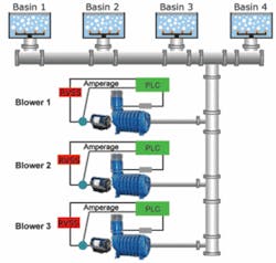
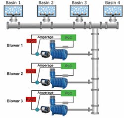
In a typical inlet throttling valve set up, a centrifugal blower is operated at a fixed speed and the amount of air entering the blower is physically modified. A normal fixed speed configuration includes some form of starter, such as a reduced voltage soft start (RVSS), which starts the blower and slowly increases the speed to full. A RVSS is necessary because the mass of a centrifugal impeller can cause extreme physical and electrical stress if instantaneous starting is attempted. Furthermore, an RVSS can diminish demand charges by minimizing the inrush during a motor start. However, when a RVSS is at full speed, it produces maximum heat for a sustained period. A bypass contactor will minimize heat production and result in a smaller enclosure.
In addition to the starter or RVSS, other equipment is necessary to detect the surge point and motor overload point of the blower. Information from these devices is used with the control system to ensure that the blower operates in its valid range. Finally, air control is accomplished via a valve that is placed in the blower inlet pipe.
An inlet throttling valve system has several limitations to efficient control. When a blower runs at a constant speed, the surge point is at a fixed airflow and amperage at that speed. Thus, control must occur between that point and the maximum amperage of the blower.
Mechanical butterfly valves often are used in inlet throttling valve systems. These valves are cost effective but don’t have a linear modulation response. Complicating matters is that valve positioning equipment is a hybrid of mechanical and electric devices. These devices often are not capable of providing tight control. To compensate, the control program in the PLC has to be very loose to ensure stable control, but loose control inherently wastes energy. Therefore, this combination of valve, positioning equipment and loose control program can prevent tight control near the blower’s surge point. Operating a blower in the region just above the surge point results in significant energy savings.
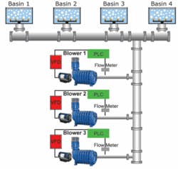
Unlike an inlet throttling valve system where the blower operates at a fixed speed, VFDs regulate the speed of the centrifugal blower which modifies the amount of incoming air. Therefore, a VFD control scenario does not require valves or guide vanes for air modulation. Also, due to the electrical nature of VFDs, they can provide extremely tight control over the speed of a blower, and thus airflow. This means a tighter control program can be created, enhancing energy savings.
Furthermore, when using a VFD the surge point of the centrifugal blower is not fixed. This means that additional energy savings can be garnered. When a blower’s speed is decreased, the blower curve shifts. The net result is that the surge point decreases as the blower speed decreases. Therefore, a blower controlled by a VFD has a greater operating range than an equivalent constant-speed blower. This enhanced turn down is on the low end of the operating range where there are greater efficiencies. The closer you can run the blower to its surge point the more efficient it will be because the surge point is where the amperage is lowest. The tighter control of a VFD allows stable operation closer to the blower’s surge point. A lower motor speed means less energy consumption.
How Much Energy Can Be Saved?
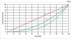
A general rule of thumb to follow is that a centrifugal blower delivering 80 percent of its rated speed only requires 50 percent of the rated power. The affinity laws state that there’s a cubed relationship between speed and power. Figure 1 demonstrates the relationship between flow and power requirements of a centrifugal blower.
Consider the following examples:


