Cavitation in Pilot-Operated Automatic Control Valves
By Brad Clarke and Kari Oksanen
Cavitation can be an extremely damaging force as related to the application of pilot-operated automatic control valves. The consequences of cavitation are numerous and can include: loud noise, extreme vibrations, choked flow, and destruction or erosion of control valves and their components, resulting in disruption of water distribution or plant shutdown.
Cavitation consists of rapid vaporization and condensation within a liquid. When local pressure falls to vapor pressure (approximately 0.25 psi/0.018 bar absolute for cold water), vapor bubbles are formed and when these bubbles travel to an area of higher pressure, the bubbles collapse with phenomenal force and great localized stress. It is the violent collapse of these vapor bubbles near valve components or downstream piping surfaces that cause cavitation damage and subsequent performance degradation.
Typically, the reason for low pressure is that the pressure drop across a control valve has created very high velocity in the seat area and corresponding low pressure because potential (pressure) energy is reduced to compensate for the increase in kinetic energy. This principle, known as Bernoulli’s Principle was named after the mathematician Daniel Bernoulli and was first published in 1798 in his book, Hydrodynamica. The principle can be applied to various types of fluid flow and simply states that when there is an increase in the velocity of fluids then it must be accompanied by a decrease in the fluid’s pressure; the total energy associated with the flow must remain constant. In scenarios where the pressure drops to vapor pressure, cavitation will occur.
In control valves, the pressure drop typically occurs at or near the seat area or just downstream. The shock waves and pressure fluctuations resulting from these high-velocity bubble collapses can also cause noise, vibrations, accelerated corrosion, and limited valve flow. Typically the cavitation is formed in the valve throttling area; the pressure fluctuations radiate into the downstream pipe as noise. As the cavitation increases, the magnitude of these pressure fluctuations also increase. System vibrations, pipe wall vibration, and component damage will increase accordingly. The associated results can cause erosion of either the control valve components or alternately the downstream piping in the vicinity of the control valve.
Cavitation is not always easy to predict. One factor worth noting is that cavitation will increase with increasing fluid temperatures. Cavitation can also manifest when liquid at a high velocity is trying to make a sharp bend. Flow separation from the solid boundary creates low pressure and cavitation.
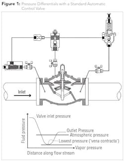
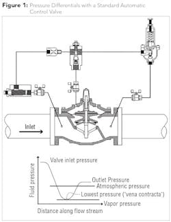
Figure 1 demonstrates how a standard pilot-operated automatic control valve incurs cavitation when extreme pressure differential occurs through the valve flow path. Please note the highest velocity/lowest pressure “vena contracta” within the actual valve and the subsequent outlet pressure and flashing (which is a combination of fluid and vapor) demonstrating the destructive forces of cavitation at work. The cavitation process will occur regardless of coatings such as two-part epoxy or heat fusion epoxy. Valve metallurgy also has an impact on cavitation and the valves referenced in this article are typically made from ductile iron or cast iron. Other materials such as stainless steel generally have much superior tolerance to the effects of cavitation.
Predicting Cavitation
Many manufacturers of pilot-operated valves have the ability to assist in predicting cavitation and defining what conditions should be of concern. Often this information can be found in technical product catalogs. The cold water cavitation coefficient is an approximation that many manufacturers use for reference.
Cold Water Coefficient (o’) = Downstream Pressure (P2) - Vapor Pressure (Pv)
Differential Pressure (∆P)
In the case of globe style valves, damage can occur when the cold water coefficient is less than the 0.7. This roughly translates to a 3:1 ratio indicator, which is a rule of thumb that Singer Valve uses to flag applications that require careful consideration for implementing a variety of techniques to overcome or contain cavitation.
Solutions to Cavitation
Multiple Valves
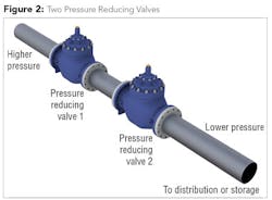
Before the introduction of anti-cavitation trim and anti-cavitation chambers in the pilot-operated control valve industry some 30 years ago, it was common practice to utilize two or more control valves in a series. Manufacturers that do not provide anti-cavitation trim will still recommend this approach. The concept behind this practice is to break the pressure into multiple stages using two or more control valves.
Figure 2 shows two pressure reducing valves being utilized with the most efficient design to reduce approximately 2/3 of the pressure drop through the first PRV and the remaining 1/3 of the pressure drop through the second PRV. This approach can be effective in eliminating cavitation. The primary disadvantage of this approach is economics. Instead of one pressure reducing valve, two isolation valves, bypass control, pressure gages, concrete chamber and associated equipment as well as labor for installation, you would now be doubling the cost of the complete equipment and installation along with increased space requirements.
Orifice Plate
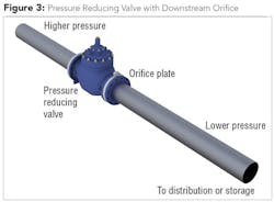
A second example of managing cavitation is by utilizing a properly sized orifice plate to the downstream side of a single pressure reducing valve (see Fig. 3). This means of controlling cavitation is only effective if you have unchanging flow rates. Great care needs to be given in sizing the orifice plate as the first stage reduction is achieved in the standard pressure reducing valve while the second stage reduction is achieved through the use of the orifice plate. If the pressure differential across the orifice plate exceeds the rule of thumb (3:1 ratio) or if the valve and orifice plate discharge to atmosphere at more than 25 psi/1.7 bar, then cavitation will occur and will migrate downstream.
Dual Cages with Pre-Set Elongated Slots
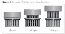
This approach is a sound suppressor rather than cavitation fighter and is an off-the-shelf solution that is not typically engineered for a specific application. In this approach, each size of control valve has a standard cage offering with pre-set elongated slots, which means a single size must be used for all applications. There are often published limitations for this approach such as “For atmospheric discharge, the maximum inlet pressure cannot exceed 150 psi/10.3 bar” amongst others. When selecting this type of anti-cavitation solution, full attention must be given to “Notes on Operating Differential.” If this is exceeded, the predetermined size of the discharge slots (large by comparison) may allow vapor bubbles to migrate downstream without collapsing within the cage.
Figure 4 depicts the elongated slots in three simulated flow positions: closed, half open, and fully open. When reviewing manufacturers’ literature, exercise caution when statements like “Virtually Cavitation Free Operation” are used. If an inadequate solution is implemented, often the only recourse is to add a second pressure reducing valve or retrofit an orifice plate downstream of the suspect valve. Another concern is the size of the actual cage and the resulting Cv difference. In order for the cage to be received by a given body of the main valve, the cages of the elongated slotted version tend to be substantially smaller than an equivalent-sized version of an engineered orifice style cage. Always check Cv values and maximum flow required when choosing a valve size; never select a valve solely on the existing pipeline size.
Dual Cages with Pre-Set Orifices
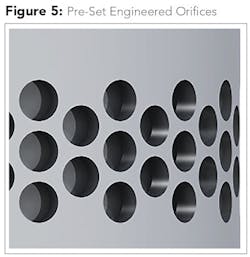
This approach is very similar to the dual cages with the pre-set elongated slots except that the water flows through orifices and not slots (see Fig. 5). With this design the cages are engineered with orifices that follow a pre-set pattern and do not take into account the specific flow and pressure data of a particular application. The outer cage modulates with changing flow and should supply the maximum catalogued flow rates. As this is not an engineered solution specifically for each application, great care should be taken in ensuring that the given application falls well within the manufacturer’s catalogued data.
Dual Cages with Engineered Orifices
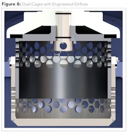
The most successful approach is an engineered solution for each application, which requires that specific flow ranges, inlet pressure ranges and outlet pressure requirements be supplied. The data is then entered into proprietary engineering software that calculates the size and placement of the orifices on both inlet and outlet cages. Figure 6 depicts the double cages with engineered orifices. The outlet cage modulates with changing flow and will supply the requested maximum flow rates.
Since this is an engineered solution, the limitations that other styles of cages demonstrate are not a factor. Extreme pressure drops, even to atmosphere, can easily be handled with this technology. The engineered orifice approach has numerous advantages:
- Multiple engineered orifices have quicker recovery and cavitation. Collapse occurs close to the orifices, inside the cages, with reduced risk of carryover downstream of the cage.
- Adjusting the number and size of orifices allows the control of pressure inside the cages and therefore cage to downstream to prevent secondary cavitation.
- Customizing the orifices ensures sufficient pressure inside the cage to open the valve (i.e., bonnet pressure is greater than or equal to downstream, so downstream pressure is of no help in opening).
- Customizing the orifices can reduce the rate of change of flow when partly open to reduce closing surges.
- With given flow velocity, the larger diameter cages provide more dwell time to collapse or contain recovery (which, if carries over downstream, is damaging).
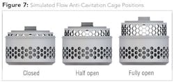
The dependability of this technology is only limited to the accuracy of the engineering data supplied for each application. In Figure 7, the cage is depicted in three positions: closed, half open, fully open.
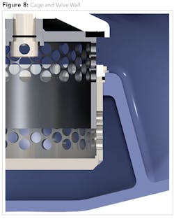
In Figure 8, note the large separation between the wall of the valve and the anti-cavitation cage. The bodies of the engineered orifice design are specifically designed to fit a larger cage, allowing higher Cv values (increased flow) while the body is designed to allow reasonable space between the anti-cavitation trim and the body wall. This separation allows for even, uniform entry around the cage area, ensuring the vapor bubbles collapse symmetrically towards the center of the anti-cavitation cage.
If there is not sufficient space between the cage and the wall of the valve, flow into the cage area may be restricted, offsetting the central collapse of the vapor bubbles and forcing the vapor bubbles to the extremity of the upper cage, potentially encouraging the escape of these vapor bubbles downstream.
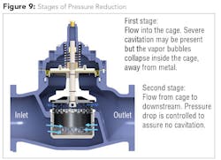
Figure 9 depicts the flow of water and stages of pressure reducing with this type of engineered anti-cavitation trim.
Most manufacturers have taken advantage of stainless steel cages, with preference for grade 316 stainless over 303/304 stainless steel due to superior corrosion characteristics. It’s recommended that material specifications be checked in detail.
About the Authors: Brad Clarke is vice president of sales and marketing for Singer Valve, and Kari Oksanen is the company’s general manager. Please visit www.singervalve.com for more information.
More WaterWorld Current Issue Articles
More WaterWorld Archives Issue Articles
