Computational flow: modeling applications expand into the water industry
Computational Fluid Dynamics (CFD) is used in the design and analysis of systems, processes and components. Dr. Robert Harwood of Fluent, Inc., provides an overview of CFD modeling techniques and the ways in which they can be applied in the water industry.
by Dr. Robert Harwood
Computational Fluid Dynamics (CFD) is essentially a computer-based method used to solve fundamental governing equations of fluid dynamics - continuity (conservation of mass), momentum and energy equations. This approach to flow modeling is not new; it has not been practicable in many cases. Only in the last two decades has the CFD service industry developed, and this can be principally attributed to the rapid increase in computing power and associated software packages.
Governing equations of fluid mechanics can be solved in several ways depending on the approach adopted, for example, finite difference, finite volume or finite element. A CFD modeling approach typically consists of three stages --
- Pre-processing. In this stage, the geometry of the structure to be modeled is defined. A computational mesh is then created within the defined geometric boundaries. The mesh nodes or cell volume centers are the locations at which the discretized governing equations are solved in the next stage of the process.
- Solving. The model boundary conditions, physical properties of the fluid and the operating conditions for use in the model are specified. If appropriate, a turbulence model is also specified. Using this information, the software computes the flow field within the defined geometry. The results are examined in the post-processing step.
- Post-processing. The computed flow field can be visualized in a number of ways. These include velocity vector and velocity magnitude plots on surfaces and planes within the defined structure. Data can also be displayed in numerical format.
Advantages of using CFD
A modeling approach that includes the use of CFD can yield significant benefits to the user. These can include:
- Speed and efficiency. When compared with more traditional techniques such as physical modeling, CFD enables the desktop PC to become the laboratory and scale effects can be eliminated. The performance of many alternative configurations of a system operating under a wide range of conditions can be assessed more rapidly. The time to market for new products, therefore, can be reduced. An approach using CFD meets the needs of the Water Industry in today’s climate of optimization with the need to satisfy both compliance and value business drivers.
- Cost savings. The speed and efficiency savings thus gained can lead to direct cost savings. In the design and development process at Hydro International Ltd, CFD simulation has been used to assess the relative impact of design change on a hydrodynamic separator yielding direct savings in fabrication costs.
- Knowledge. By simulating the flow within or around a structure the engineer can gain significant insights into the behavior of the system modeled. Data can be obtained from a CFD simulation that cannot easily or accurately be measured in physical model studies. In this way the causes as well as the effects of system behavior can be determined.
*Troubleshooting. In cases where poor system performance has been identified, the knowledge gained from CFD simulations of the system can be used to determine the cause of the poor performance and to determine appropriate remedial action
Limitations of using CFD
As with any modeling technique, it is important to understand the limitations of the approach and the restrictions that limit its use. CFD should be applied according to recommended guidelines and with models that are applicable to the situation. Clearly, inappropriate input will yield inaccurate and possibly non-physical results.
The physics of the problem should be understood in order to carry out a successful, comprehensive CFD simulation and analysis. In some cases the rheology of the material may not be known or representative data may not be available, as is the case for some sewage sludges or aesthetic particles. Therefore, to carry out a CFD analysis, it may be necessary to make simplifying assumptions.
A recent comparison of physical model studies of the performance of combined sewer overflow (CSO) chambers with those carried out using CFD identified two analogies between the approaches (R Harwood, A J Saul: “Modeling the Performance of Combined Sewer Overflows, Combined Sewer Overflows - The Challenge and Latest Innovations,” CIWEM National Conference, The University of Sheffield, 13th September 2000). These were model construction and retention efficiency prediction. In terms of the former analogy, it was stated that to provide an accurate simulation of the flow field within the chamber, the construction of a physical model is required to satisfy appropriate scaling laws. In a similar way, it is essential to build or construct the elements of a CFD model in a manner that ensures accurate predictions. In terms of the prediction of the retention efficiency performance of a CSO chamber, it was stated that neither an off-site physical scale model nor a CFD model could give a prediction of the absolute in-situ particle retention efficiency performance of a CSO chamber. Both techniques are therefore restricted to giving an indication of chamber performance, assessing “what if?” scenarios and providing a basis for comparative chamber performance assessment in terms of non-representative particles.
CFD and the water industry
CFD can be used to model the flow pattern within impounding reservoirs. In this way areas of sedimentation, stagnation zones and regions of flow short-circuiting can be identified. The effects of surface wind can also be investigated. Further studies can be carried out to determine the optimum location for proprietary equipment, such as aerators.
Screens and filters can be represented in several ways in a CFD model. Typically a porous zone will be used to represent the pressure loss across a screen. In this way, for example, CFD modeling can assist with the design or with remedial strategies for loading rate equalization.
In these processes, good mixing of the influent and the coagulant is essential. A CFD model can be used to investigate the mixing caused by different impeller types and to identify optimum placement of the mixers.
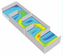
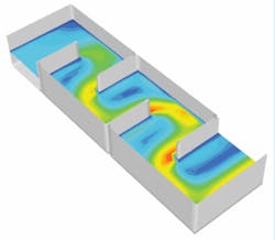
Multiple phase simulations can also be tackled using CFD and hence the performance of settlement and clarification tanks can be assessed. Several approaches are available and possibly the simplest involves simulating the trajectory of a number of discrete particles of user specified terminal velocity.
CFD simulations can be carried out to rapidly determine the residence time distribution curves for contact tanks. In addition, user specific models can be implemented to study the effects of the decay in concentration of an injected tracer with time.
In practice, service reservoirs are often constructed from a structural rather than a hydraulic perspective. Problems such as flow short-circuiting and the formation of flow dead zones are therefore common. CFD can be used to rapidly simulate the flow pattern within such structures and to assist in the formulation of remedial actions if necessary. CFD can be used to model the performance of many of the structures commonly used to intercept surface runoff or the combined flow of surface runoff and sewage. These include oil/water separators, detritus and grit traps, storm overflows, combined sewer overflow (CSO) chambers and other in pipe/sewer processes.
Most of the common processes within a wastewater treatment works can be modeled using CFD in some way to yield direct benefits for the design or process engineer. These include sedimentation tanks, aeration tanks, clarifiers and filters. Other common applications include flow splitter chambers where CFD can be used to determine the distribution of flow between process components.
The effect of a discharge on the local flow pattern within a river can also readily be simulated using CFD. Similarly, the mixing of the discharge stream can be assessed.
Author’s Note
Dr. Robert Harwood is an engineer at ANSYS-Fluent Inc., based in Lebanon, New Hampshire, USA. For more details on CFD technology and the Johnston Pipes Ltd. case study, visit http://www.fluent.com.


