By Allan R. Budris, P.E.
Introduction
Water hammer is a very destructive force that can exist in any pumping installation where the rate of flow changes abruptly for various reasons. Most engineers recognize the existence of water hammer, but few realize its destructive force. In fact, much time and expense have been spent repairing pipelines and pumps damaged by water hammer. It is thus essential for an engineer to know when to expect water hammer, how to estimate the possible maximum pressure rise, and if possible, how to provide a means for reducing the maximum pressure rise to a safe limit.
A water supply system is subjected to water hammer whenever there is a change in steady-state condition such as pump stoppage, pump startup or valve closure. As a system changes from one steady-state condition to another, there is a transient change in flows and pressures as the system settles to the final steady-state condition. The magnitude of transient pressure (or water hammer) and the time duration of the transient condition depends on the flow-rate velocity, pipeline material and the system boundary conditions such as tanks, pumps, air valves, control valves, and changes in pipeline diameter.
Water Hammer (Hydraulic Inertial Head)
If a system contains an appreciable amount of liquid, the inertia of the liquid mass could offer a significant resistance to any sudden change in the velocity. Water hammer is an increase in pressure due to rapid changes in the velocity of a liquid flowing through a pipeline, and this could cause rupture or damage to the pump, piping or fittings.
This dynamic pressure change is the result of transformation of the kinetic energy of the liquid moving mass into pressure energy. When the flow of liquid is suddenly stopped, the liquid tries to continue in the same direction. In the area where the velocity change occurs, the liquid pressure increases dramatically due to the momentum force. As it rebounds, it increases the pressure in the region near it and forms an acoustic pressure wave. This pressure wave travels down the pipe at the speed of sound in the liquid. If we assume the liquid is water, rigid pipe and ambient temperature, the wave velocity is 4,720 ft/sec. Further, the acoustic wave will be reflected when it encounters an obstruction, such as a pump, fitting or valve.
System actions that can precipitate water hammer include:
- Fast startup or shutdown of pumps
- Fast closure/opening of valves
- Power interruptions
- Check valves slamming shut on reverse flow
- Water column separation
Estimating the Magnitude of Water Hammer Energy Spikes
The momentum force due to water hammer is a function of the speed of valve closure, the liquid velocity in the pipe prior to the start of valve closure, and the velocity of the pressure wave along the pipe. The magnitude of this pressure wave also depends upon the ratio of the wall thickness to the inside pipe diameter, the modulus of the pipe material, and the modulus of elasticity of the liquid.
Surge pressures on shutdown may range from the pump shut-off head to impact heads five or six times normal static pressures, or even more. Similar surge pressures are encountered on startup. Resulting damage actually experienced has included deformed check valve discs, bent or broken pump shafts, damaged impellers, and cracked or broken mains. Less obvious or easily attributable effects may include shortening of the life of the piping systems and acceleration of the frequency of leaks.
If the time of valve closure, in seconds, is greater than the total length of pipe (L), in feet, divided by 1,000, then momentum theory (Newton's second law of motion) applies:
| Fm = (p/g)Q(V1 – V2) |
| Where: |
| Fm = Momentum force (lbsf) |
| p = Fluid density (lbs/ft3) |
| g = Acceleration due to gravity (32.2 ft/sec2) |
| Q = Rate of flow (ft3/sec) |
| V1 = Initial velocity (ft/sec) |
| V2 = Final velocity (ft/sec) |
On the other hand, if the time to close the valve is less than L/1,000, then the acoustic shock wave/elastic column theory applies. In this case:
| P = p x A x V / (g x 144 in2/ft2) |
| Where: |
| P = Pressure rise (psi) |
| p = Liquid density (lbs/ft3) |
| A = Velocity of sound in water (ft/sec) |
| V = Velocity of the liquid in the pipe (ft/sec) |
| g = Acceleration due to gravity (32.2 ft/sec2) |
As an example, if a pump is working at 200 psig, and the liquid is traveling at 13 ft/sec (the maximum recommended discharge velocity), the instantaneous pressure inside the casing would jump to 1,158 psig. This assumes that the liquid is ambient water, and the valve closure time is short enough for the elastic column theory to apply. Pump casings are not usually designed for this magnitude of pressure, especially if the casing is made of a brittle material, such as cast iron. Even if the casing is constructed of a more ductile material, the shock wave may still cause permanent deformation and ultimate failure.
The pump is not the only component that is affected by this phenomenon. Valves and pipe fittings are at risk of catastrophic damage. Pipe hangers and pump foundations can also be adversely affected by water hammer. PVC pipe and fittings are quite susceptible to damage from water hammer.
Mitigating Water Hammer Damage
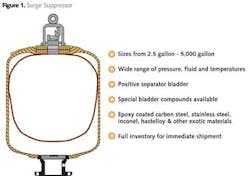
Water hammer can be controlled through proper valve closure rates (with slow-closing valves), the addition of diaphragm tanks (surge chambers, see Fig. 1), or similar accumulators to absorb the pressure surge and relief valves to release the pressure. More specifically, surge suppression can be accomplished by:


