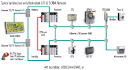
Typical Architecture with Redundant I/O & SCADA Network
Click here to enlarge imageAnother example may include the chemical feed pumps. Often a dedicated pump is provided for each of two trains, with a third swing pump for redundancy. All three pumps are programmed to automatically start and regulate speed, but the position of small PVC hand valves is not detected by the control system. This will prevent the system from starting the third pump. Perhaps a four-pump system, with a primary and standby for each train is better.
Protect Communications
If you choose to implement redundant communication, make sure that both cables do not pass through the same conduit or share a similar routing. The best technique is to provide a ring around a facility, building or process. This would protect against loss of control if a cable was severed.
Additionally, in a redundant control system, some designers put both primary and secondary chassis in the same enclosure. This design exposes both processors to the effects of a lighting strike, panel fire or an explosive short circuit event. Placing the chassis in different panels minimizes the chance of losing control.
Monitor Back-up Systems
The SCADA system, or other alarming management tools, needs to monitor the secondary systems to verify that they are powered up and ready to take control. This also includes monitoring the status of Scan- and Transfer-type synchronization to verify that it is up to date.
Power Protection
Unfortunately, it is not uncommon to see chassis of a hot standby fed from a common breaker. This is also seen where redundant power supplies share a single breaker or different phases of the same power source. If the breaker trips, or phases are lost, then both primary and secondary controllers will crash.
The question then becomes whether or not the two power supplies can be fed from the same panel board, transformer or switchgear. At some point, the concept of separating power sources becomes absurd. No one will decide to have a second utility tie-in because of a control system 120 vAC connection. However, similar, less costly alternatives may be available.
Many water and wastewater plants have utility power and generators that supply the entire plant. In this case, the highest point where commonality occurs is where you connect both controllers. For example, assume that the I/O chassis for a hot standby system are spread across multiple buildings and each building derives its own 120 vAC from a transformer. Then it makes sense to locate the primary and secondary in separate buildings.
A deeper analysis of the facility’s power distribution system may be needed to ensure redundancy. Some facilities have a split system in which a generator backs only part of the distribution network. For this type of system, you may want to have both processors located on the generator-supported power. The I/O will then have to be analyzed to determine whether it needs to be placed on the generator side, or utility-only side.
For example, a facility may use a generator to back up power for aeration basins but not sludge presses. As a result, the I/O for the aeration basins must be placed on generator-backed power, but the I/O for the sludge presses could be located on the utility-only side.
Remote I/O Network
Another consideration is to understand which network should be used for remote I/O communication. While it is important that a quality supplier’s redundant system should have remote I/O over a quad shield cable, this may not always be required in water and wastewater. Quad shield I/O systems may limit the designer to the utilization of only one method of I/O. Since many water and wastewater facilities do not need the performance requirements that a quad shield I/O system can deliver, it could make sense to use a more cost-effective I/O structure.
Today, Ethernet is becoming more and more popular for all levels of control. Many of the major suppliers, like Schneider Electric, are investing in and expanding their Ethernet communication offer. Some of these devices, such as drives, distributed I/O and I/O chassis, use Ethernet as the source of control communications. These devices represent the future path of automation—the best and most economical long-term expansion path. Any system that does not support Ethernet I/O must be carefully examined against present and future needs to determine if the system is the right choice.
Relevant Documentation
When analyzing a redundant system, do not rely solely on a supplier’s overall product catalog. Catalogs are great resources for finding general information on the products and capabilities of a supplier. However, they are not intended to be an exhaustive source of information. Find the user’s manual, programming manual and all applicable release notes. These documents may have significant information to allow you to determine which system is truly the best for your application.
Redundancy in the water and wastewater treatment industry is critical at some level to improve reliability. However, sometimes reliability is not fully examined during the design or installation stages. This is especially true for automation redundancy. By gaining a solid understanding of proven redundancy design techniques and the potential pitfalls, a municipality can ensure that the potential for system uptime is maximized. WW
About the Author: Grant Van Hemert, P.E., is an automation and control applications engineer at the Schneider Electric Water Wastewater Competency Center
Circle No. 293 on Reader Service Card


